Definition
A Gear is a rotating round mechanical part with "teeth" that mesh to transmit rotational power. They can be made of plastic or wood, but the most common material is metal, due to the wearing effect on the teeth.
There are many forms of gears that shift the axis rotation by 90 degrees
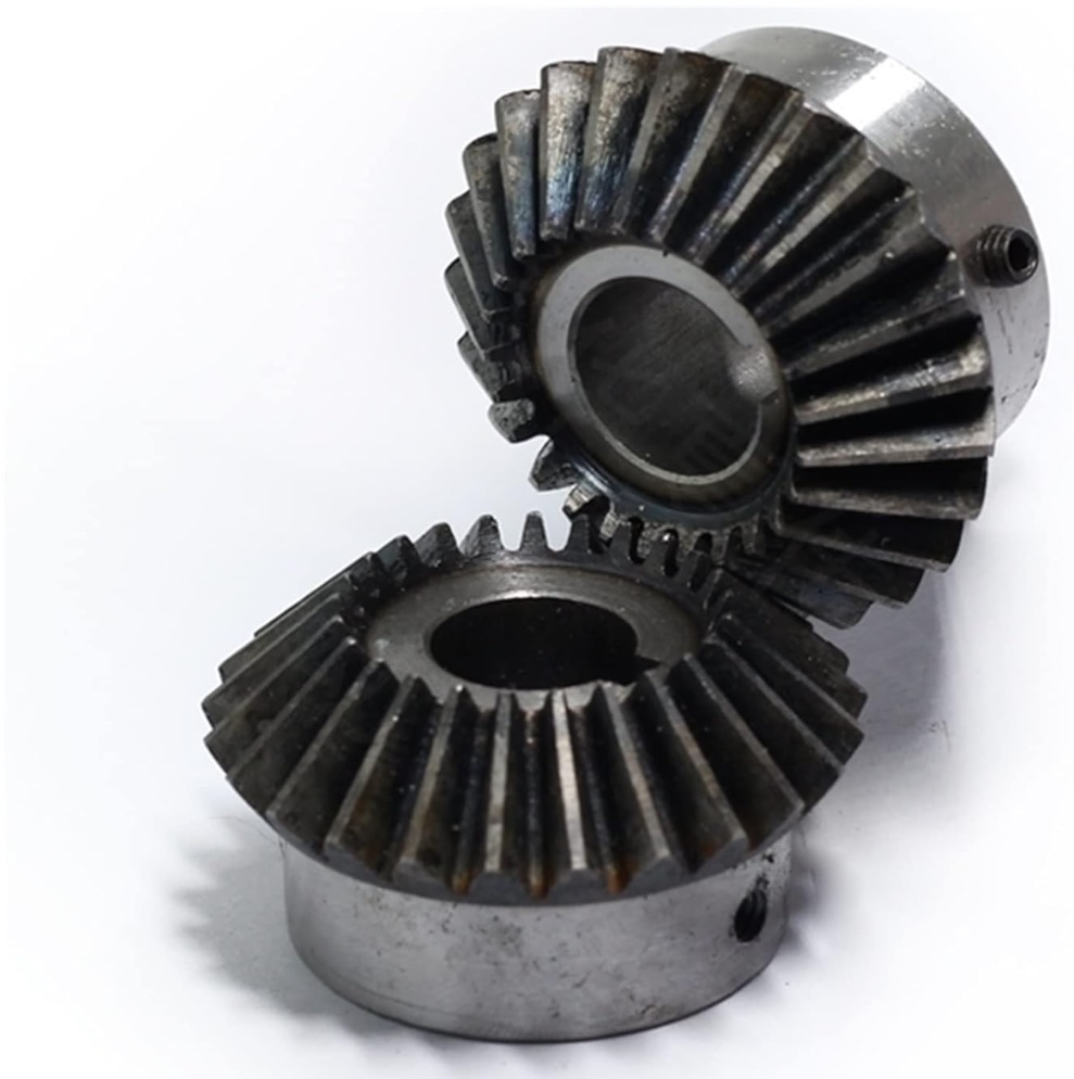
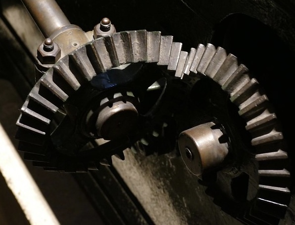
- Bevel gears are the most well-known gears sets. The driving and following gears do not have to have the same angle. Gears are often sold in pairs to deliver a specific gear ratio and angle.
- Miter gears are a subset of bevel gears where both gears have an angle of 45 degrees and the same number of teeth. This results in the two shafts rotation speed and torque being the same.
- Spiral Bevel gears are a variation where the teeth profile spirals instead of being straight. These are more complex to make, but have the benefit of distributing the contact point between the gears.
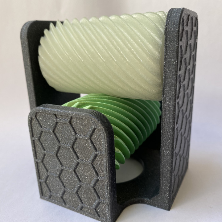
- Worm gears combine a long screw gear with a worm wheel. A worm wheel can be a simple flat spur gear, but angled or helical teeth are more efficient. Worm gears turn a full rotation to move the wheel one tooth. This results in greatly slowing down the rotation and increasing torque. Worm gears usually cannot be 'back driven', as shown by the fact that guitar strings do not unwind.
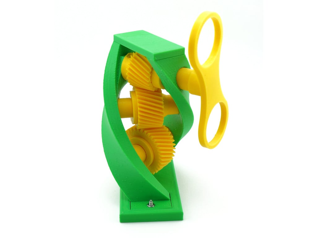
- Crossed helical gears are a unique orientation of the three dimensional helical thread. A second helical gear with matching curves can be driven by the first. Helical gears are complex to make, but very efficient as the contact point between the gears is spread across the curved threads.
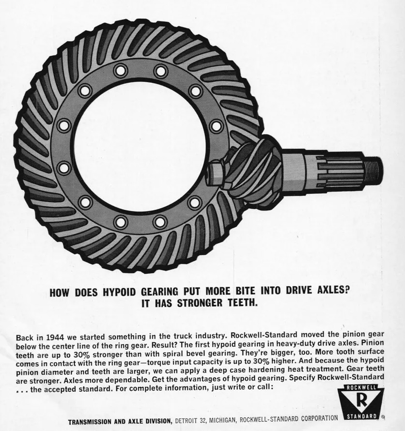
- Hypoid gears (short for hyperboloid) are "skew" gears; the shafts are neither parallel like flat gears, nor intersecting like bevel gears. Hypoid are much more complex to manufacture, but have excellent noise and efficiency. They can be found in automobile differentials.
- Cage gears are an ancient design for wooden gears, commonly found in old mills.
Key Facts
This page builds on Reduction Gear, which contains explanations for many basic gear terms and ideas. See the below Research section.
Engineering Rules of Thumb
- Keep in mind the friction losses for the total gear train. A page on efficiency Here is a 1980 paper from NASA on Spur-Gear-System Efficiency at Part and Full Load
- Lubrication is an essential part of any gearing design, poor lubrication can waste up to 8% efficiency in one report.
- Multiple Gear design calculators exist online, for example from KHK Gears
- Longevity is very important in many gear applications. You can reduce wear on the teeth when you choose odd ratios. teeth on a 50:10 ratios will meet every 5 rotations. 49:10 or 50:11 it takes many more rotations before same teeth meet and make wear more even.
- Although the most popular helix angle for screw gears is 45 degrees, any helix angle greater than zero degrees is possible.
View in 3D
Display
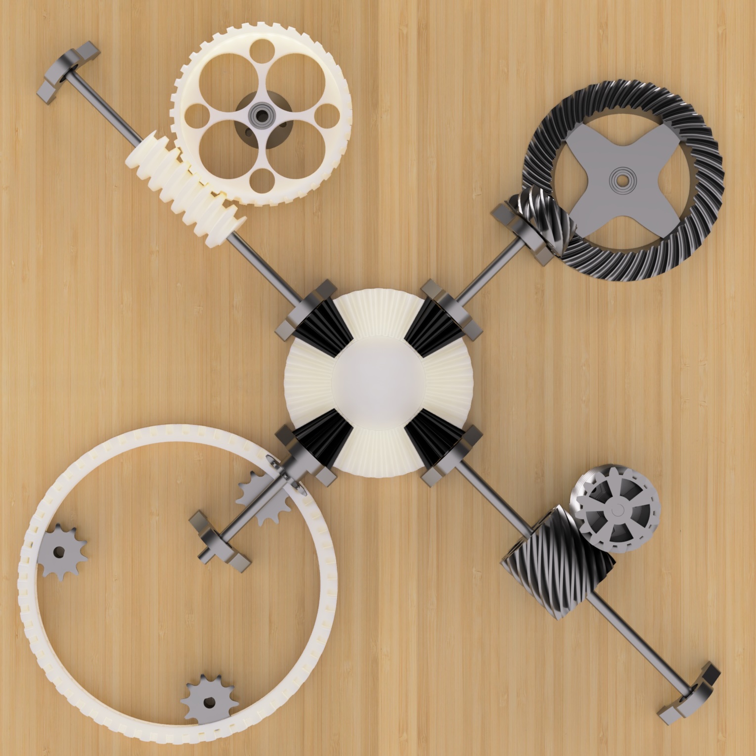
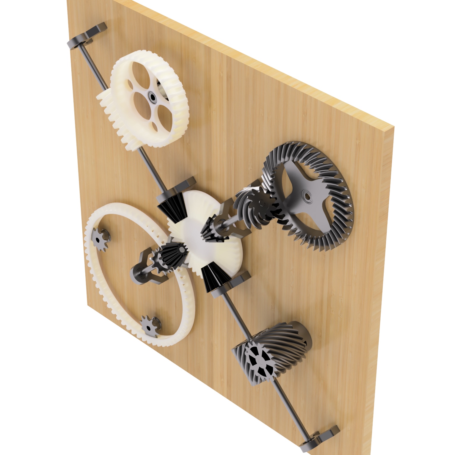
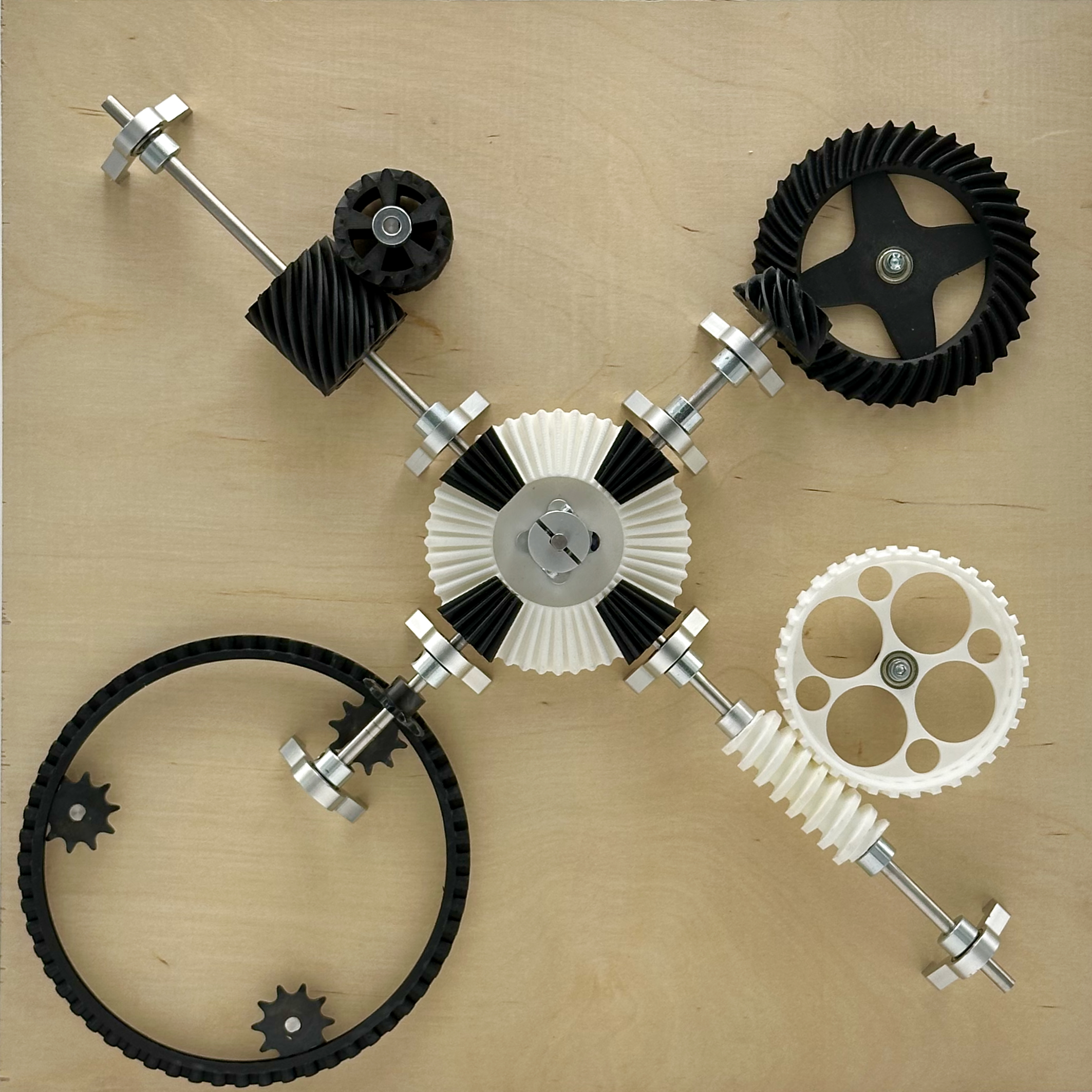
This model demonstrates different types of right angle gears.
- The driving gear in the center turns 4 bevel gears at a 48:12 (4:1) ratio.
- The top left Worm gear turns a helical ring gear at 1:36 ratio.
- The top right Hypoid gear pair at a 10:40 (1:4) ratio.
- The bottom right matched Helical gear pair at a 1:1 ratio.
- The bottom left is a fanciful Sprocket ring gear at a 10:60:10 ratio.
Images
Bevel Gears


Worm Gears


Crossed Helical Gears
Hypoid Gears

Cage Gears

Videos
Bevel Gears
Spiral Bevel Gears
Worm Gears
Crossed Helical Gears
Hypoid Gears
CAD and 3D Modeling
Gears in general
Bevel Gears
Worm Gears
Crossed Helical Gears
Hypoid Gears

Software in Fusion 360
3D Printing - files not tested
Bevel Gears

Worm Gears


Crossed Helical Gears


Hypoid Gears


Cage Gears
Mechanism in Legos
Legos have long supported gears in their models.History
Early gears were made from wood with cylindrical pegs for cogs and were often lubricated with grease from animal fat. Gears were used to change the rotational speed from water wheels or wind mills to power pumps or grain mills. The speed of a horse was typically too slow to use, so wooden gears increased the speed. Right angle gears may have preceded flat gear trains, given the large amount of friction in early machines, for example, connecting water wheels to grindstones.
The industrial revolution of the 1800's saw an explosion in the use of metal gearing. A science of gear design and manufacture rapidly developed through the century.
Reconstructing the Library Display
The Mechanical Library Gear Reduction display is composed of
- Custom Components
- (1) Custom Laser-cut 1/2" plywood panel (400mm x 400mm)
- (1) Custom 3D printed 48 teeth central bevel gear
- (4) Custom 3D printed 12 teeth central bevel gears
- (2) Custom 3D printed helical gear
- (1) Custom 3D printed worm gear
- (1) Custom 3D printed worm matching gear
- (1) Custom 3D printed sprocket gear
- (1) Custom 3D printed Hypoid pinion gear
- (1) Custom 3D printed Hypoid ring gear
- Mechanical Components
- (1) 12v 1000 RPM DC motor
- (1) 12v Power supply
- (1) Aluminum 6mm shaft coupler
- Display Structure
- (10) Gobilda 2101 Series Stainless Steel D-Shaft (6mm Diameter, 40-100mm Length)
- (20) Flanged Ball Bearing (6mm)
- (8) M4 machine Screws 18mm Length
- (1) 1120 Series U-Channel (2 Hole, 72mm Length)
- (8) 1201 Series Quad Block Pattern Mount (43-2)
- (4) Gobilda 3307 Series sprocket gear
- (?) Various M4 Screws
Research
- Excellent gear reference
- Wikipedia gear terms dictionary
- KHK Gear handbooks - excellent
- KHK on efficiency of gears
- KHK on gear module
- Cornell KMODDL (Clark & Reuleaux Collections)
- KMODDL on Archive-it.org
- Making wooden right angle gears by hand
- Wikipedia Bevel Gears
- SDP/SI gear reference
- Thanks to Dr. Stepan V. Lunin at spiralbevel.com Check out his amazing advanced gear downloads
- Wikipedia Spiral Bevel gears
- Wikipedia Worm Gears and Worm drive
- https://gearsolutions.com/departments/tooth-tips/what-is-a-worm-gear/
- https://sdp-si.com/resources/elements-of-metric-gear-technology/page4.php#Section9
- Wikipedia Helical Gear
- Thomasnet Technical paper on helical gears
- drivetrainhub.com/notebooks/gears/geometry/Chapter%203%20-%20Helical%20Gears.html
- gearsolutions.com/departments/tooth-tips/crossed-helical-gearing-a-k-a-screw-gears/
- https://www.tec-science.com/mechanical-power-transmission/gear-types/screw-gears-crossed-helical-gears/
- https://www.sdp-si.com/resources/elements-of-metric-gear-technology/page4.php
- https://roymech.org/Useful_Tables/Drive/Helical_Gears.html
- Wikipedia Skew Gear
- https://gearsolutions.com/features/why-are-todays-hypoids-the-perfect-crossed-axes-gear-pairs/
- https://en.m.wikipedia.org/wiki/Hypoid_gearboxes
- https://www.carparts.com/blog/what-are-hypoid-gears/
- Wikipedia Wooden Gears