Definition
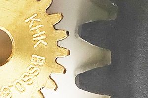
A Gear is a rotating round mechanical part with "teeth" that mesh to transmit rotational power. They can be made of plastic or wood, but the most common material is metal, due to the wearing effect on the teeth.
Teeth on gears offer several advantages over friction wheels.
- Teeth prevent slippage, so gears are always synchronized exactly with one another.
- Gear teeth are designed so that slight imperfections in the spacing of two gears are acceptable, for example if dirt gets in the machine.
- Teeth make it easy to determine exact gear ratios. You just count the number of teeth on the two gears and divide by the smaller one. So if one gear has 100 teeth and another has 10, the gear ratio is 10:1.
The Circular Pitch is the diameter of the circle where a gear meshes at. It is not immediately obvious by looking at the teeth.

Module is the circular pitch divided by the number of teeth, usually written in millimeters. Gears will only mesh if the teeth have the same module.
Diametral Pitch The number of teeth divided by the circle diameter, e.g. 2 teeth per inch. (This measurement is used mainly where feet and inches are used.) Gears will only mesh if the teeth have the same Diametral Pitch.
Pressure Angle defines how the gears contact each other, and thus how the force is distributed along the tooth. Standard pressure angles are 14.5, 20, and 25 degrees. Gears must have the same pressure angle to mesh well.
Frequency is how often a gear rotates in a set time. Typically written as RPM (Revolutions per Minute)
Period is the time for a rotation. To calculate, divide 1 by frequency.
Backlash is the slip that occurs when gears change direction, because of the spacing between teeth. Highly efficient gear trains have a small amount of backlash, but must be carefully engineered and constructed.
Torque is the measure of the rotational force applied to an object.
Key Facts
To find the Gear Ratio, count the number of teeth on the “driven” gear, and divide it by the number of teeth on the “driving” gear. If the driven gear has 100 teeth and the driving gear has 10, the ratio is 100:10 or 10:1. This is also expressed as a ratio of 10. The gear ratio can also be computed using the pitch diameter (or even the radius) using the same equation: Ratio = Output Gear Diameter / Input Gear Diameter
Gear Trains are created when two or more gears are made to interfere with each other in order to transmit power from one shaft to another. This is useful as one can get complex gear ratios by combining different gear pairs. In theory, one could create a 1,000,000,000:1 gear pair, but the first gear would be enormous!
Speed vs. Torque The key concept for gears is that speed and torque are directly related, and that gears of different sizes can control them.
If the "driving" gear is the same size as the "following" gear, the rotation rate and torque of the second remains the same. However, if the driving gear is twice as big as the following gear (2:1), the following gear will spin twice as fast and have half the torque.
In machinery, it is common to have a less powerful but fast spinning motor use a small gear to drive a larger gear with great torque. In other cases, because a motor can only turn so fast, a large to small gear ratio can make the output much faster, but with less torque.
The transmission in a car is a device that switches different output gears so a motor can drive both slowly (first gear), or on highways (4th gear), or even in reverse. This is more obvious in a Manual transmission, but the same principle happens in "automatic" transmissions. See below for an animation.
Engineering Rules of Thumb
- Keep in mind the friction losses for the total gear train. A page on efficiency Here is a 1980 paper from NASA on Spur-Gear-System Efficiency at Part and Full Load
- Lubrication is an essential part of any gearing design, poor lubrication can waste up to 8% efficiency in one report.
- Multiple Gear design calculators exist online, for example from KHK Gears
View in 3D
Display
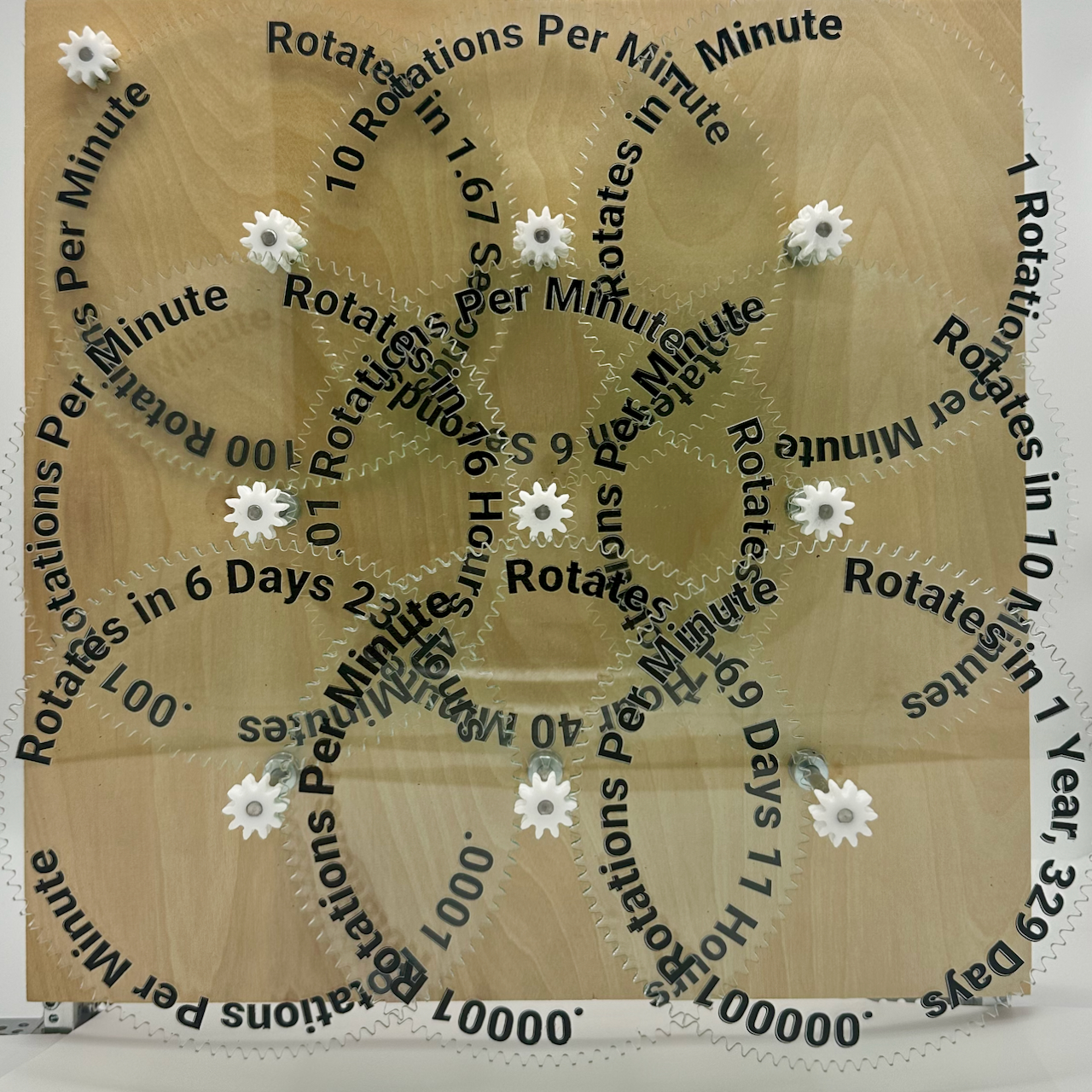
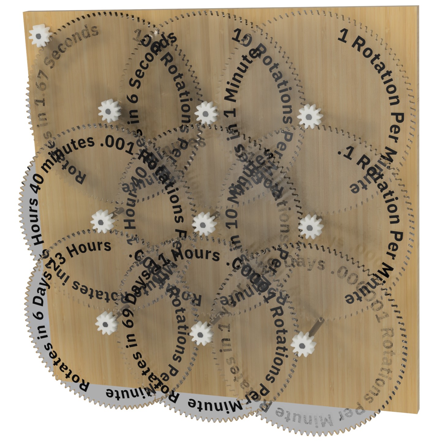
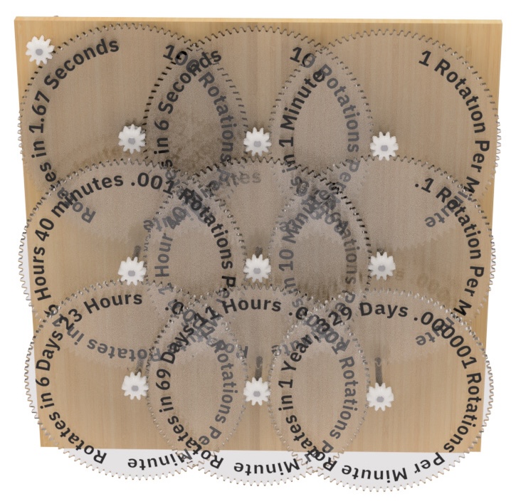
This model has a "Gear Train" of 10 gears. The driving gear (in the top left) spins at approximately 1000 Rotations Per Minute (RPM). It drives a larger gear with 100 teeth, so the ratio is written as 1:10. There are 9 other 1:10 gear pairs, so the final gear spins at .000001 RPM, which takes 1 year and 329 days of continuous operation to spin once around.
Images

Videos
3D Printing
Mechanism in Legos
Legos have long supported gears in their models.- Lego Gear Ratio Calculator with speeds and torque
- Lego Gear Ratio Calculator, works backwards from desired reduction
- Lego Educational material on Gears

History
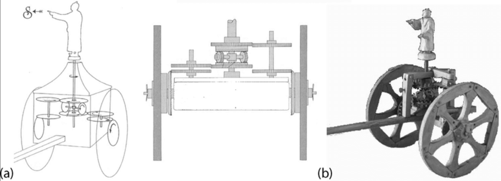
Early gears were made from wood with cylindrical pegs for cogs and were often lubricated with grease from animal fat. Gears were used to change the rotational speed from water wheels or wind mills to power pumps or grain mills. The speed of a horse was typically too slow to use, so wooden gears increased the speed.
The industrial revolution of the 1800's saw an explosion in the use of metal gearing. A science of gear design and manufacture rapidly developed through the century.


Reconstructing the Library Display
The Mechanical Library Gear Reduction display is composed of
- Custom Components
- (1) Custom Laser-cut 1/2" plywood panel (400mm x 400mm)
- (9) Custom Laser-cut 3/16" Acrylic Gears
- (20) Custom Laser-cut 1/4" small Acrylic Gears
- (10) Custom Laser-cut 1/4" clear Acrylic Supports
- (1) Custom 3D printed motor mount
- Mechanical Components
- (1) 12v 1000 RPM DC motor
- (1) 12v Power supply
- (1) Aluminum 6mm shaft coupler
- Display Structure
Research
- Model: 074 Worms and Gears on Cornell University KMODDL (from Clark Collection)
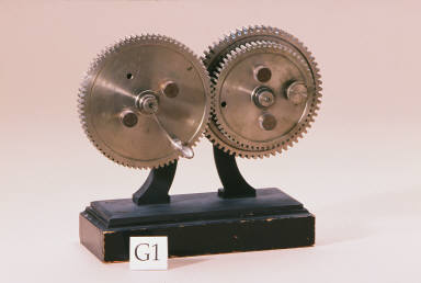
- Model: G01 Compound Gear Train, Cornell KMODDL (from Reuleaux Collection)
- Wikipedia Gears
- Torque
- Gear Train
- More on Gears
- KHK Gear handbooks - excellent
- KHK on efficiency of gears
- KHK on gear module
- Gear History
- Gear Trains
- Gear Nomenclature