Definition
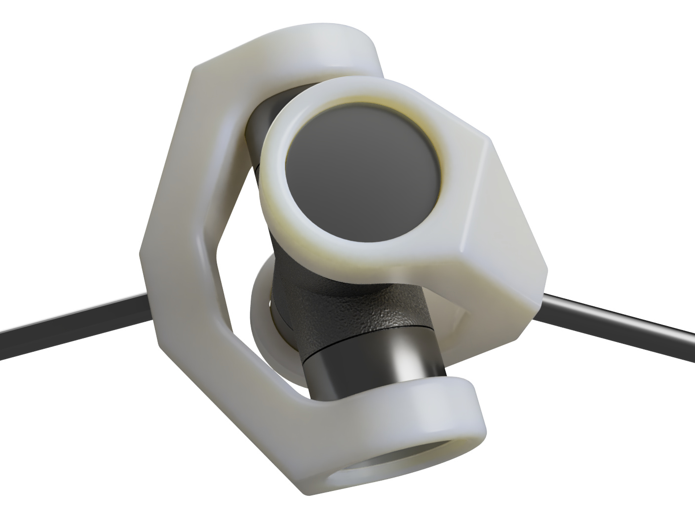
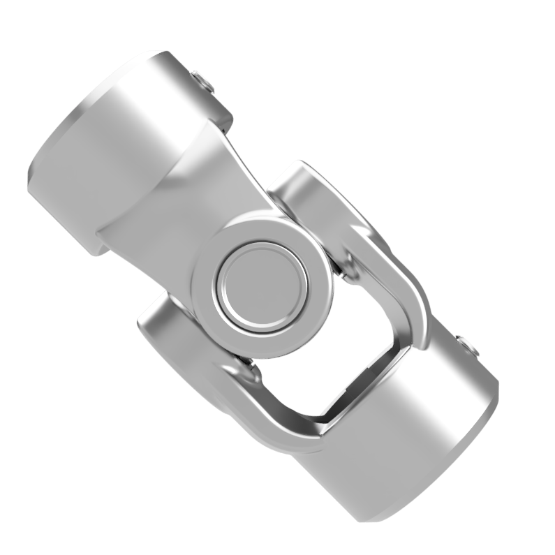
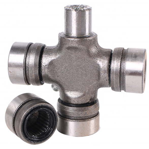
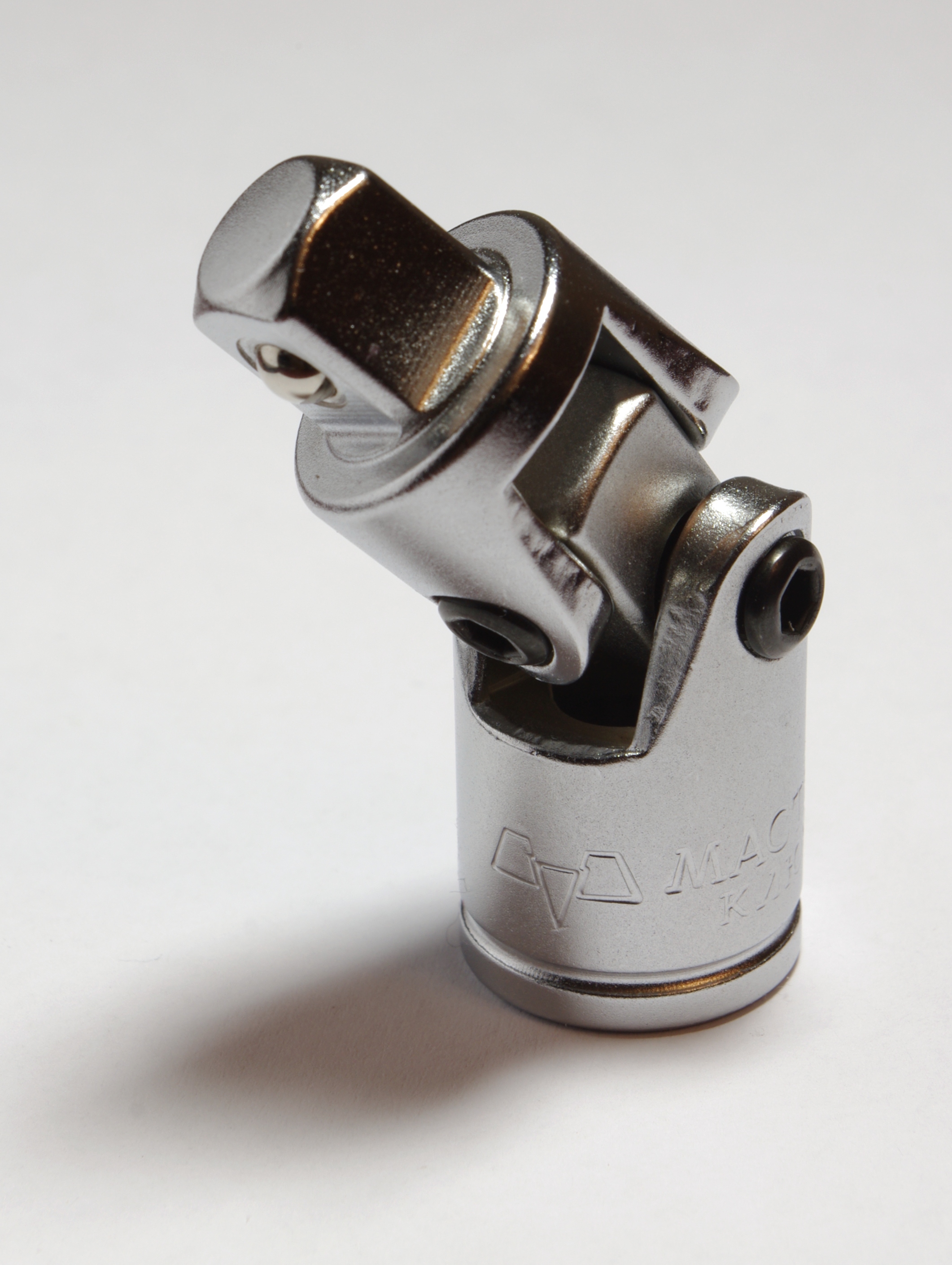
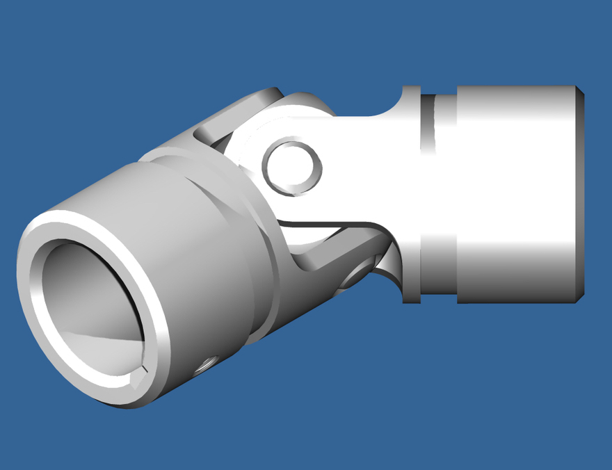
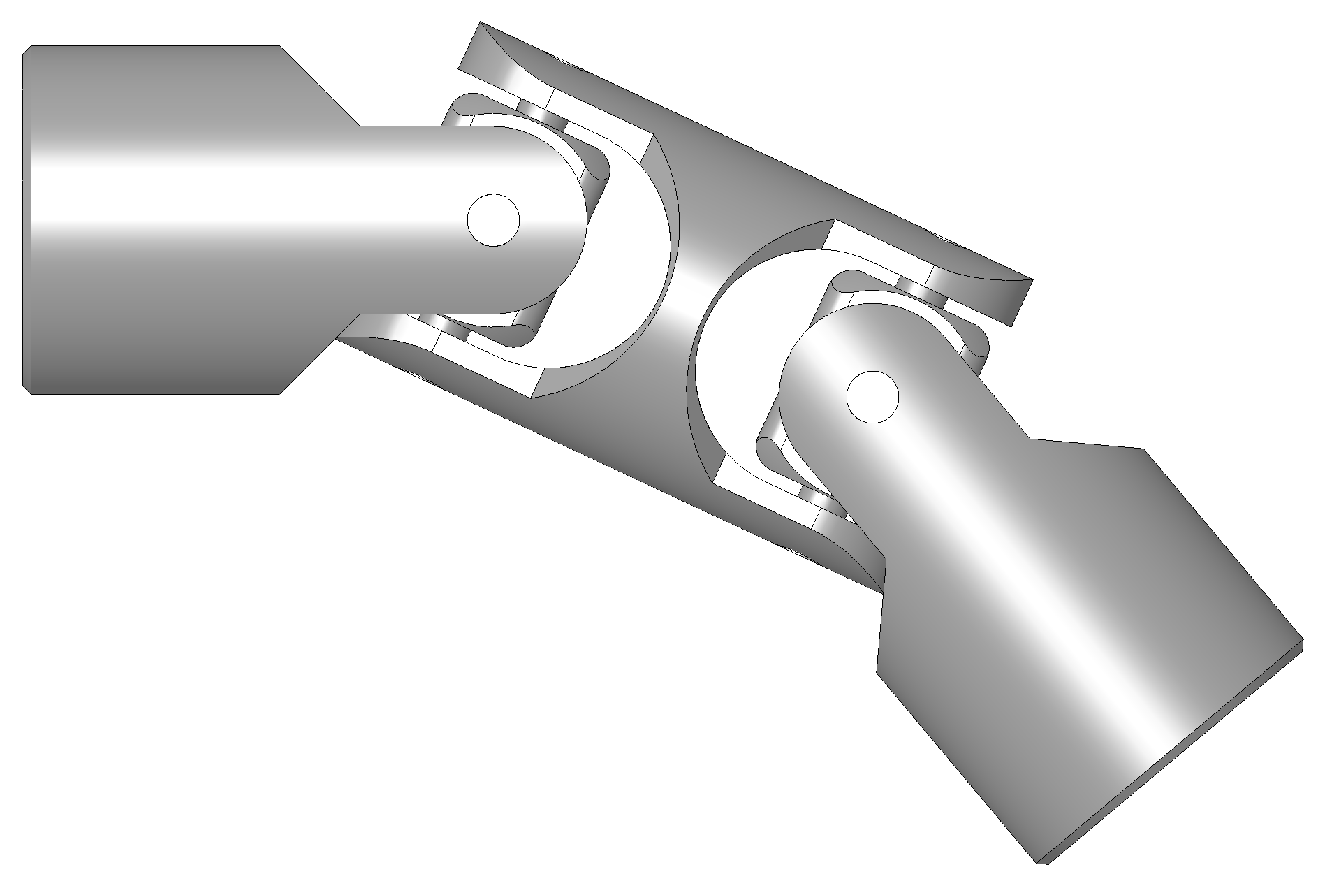
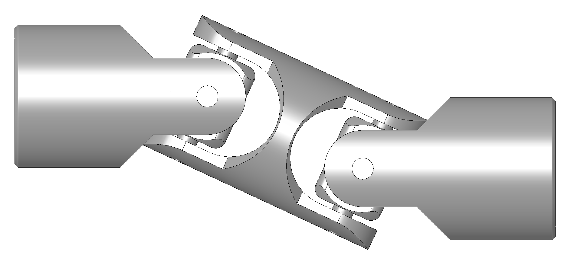
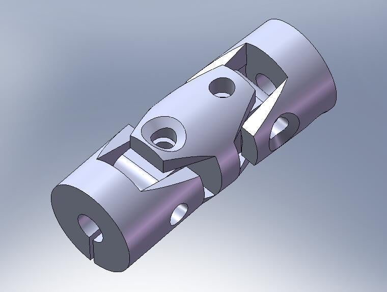
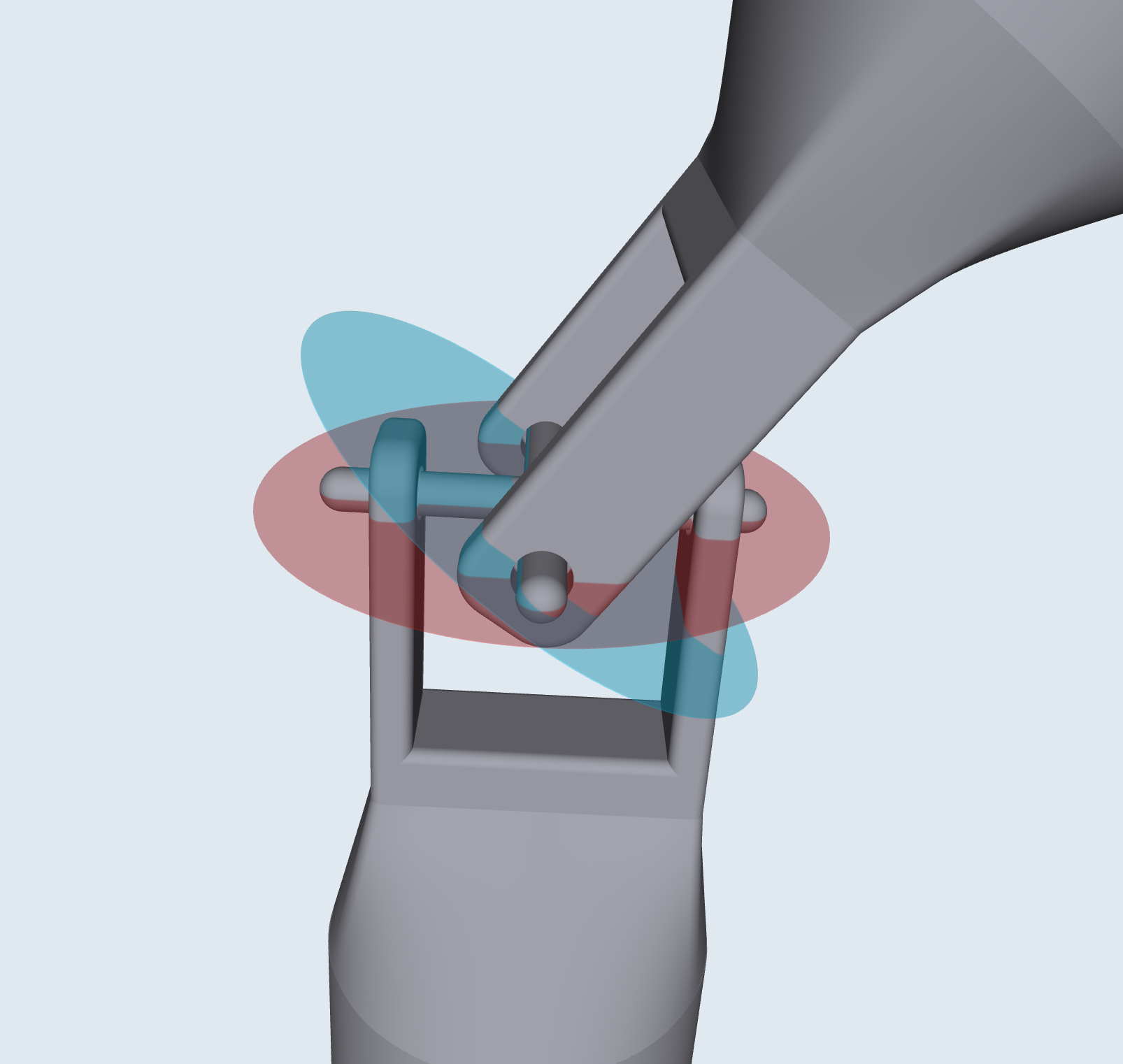
A universal joint (U-joint) is a mechanical joint connecting shafts to transmit rotary motion. It consists of a pair of hinges located close together, oriented at 90° to each other, connected by a cross shaft.
Key Facts
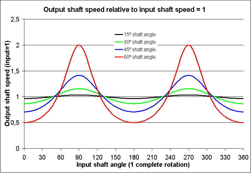
- The rotational velocity of the output shaft is not constant. It will speed up and slow down during a rotation, causing wobble. The greater the angle, the bigger the wobble.
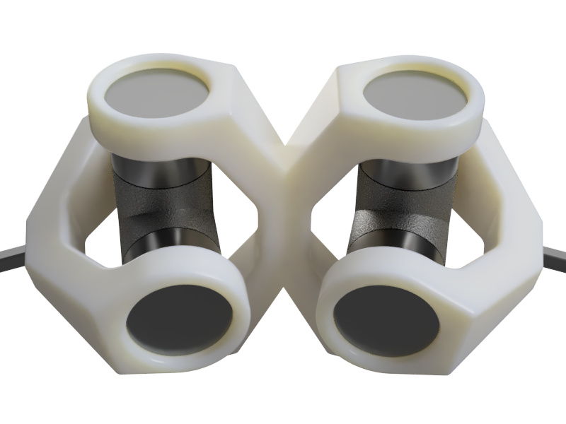
- You can eliminate the wobble by putting 2 universal joints together, also known as a “Double Cardan Joint”.
- There are other joints that are 'constant velocity', but are more complex (see other mechanisms)
Engineering Rules of Thumb
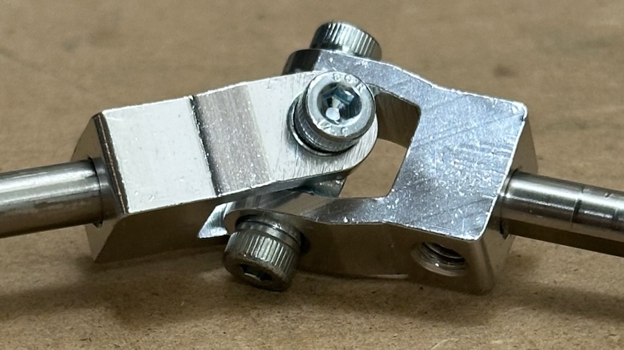
- One generally wants to keep the angle below 35°, with a max angle of 45°.
View in 3D
Walkthrough
A 3D walkthrough of the universal joint that can be rotated. Works best fullscreen. If on phone, use landscape mode.
Display

Images


Videos
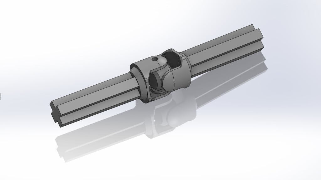
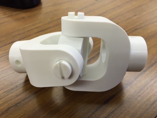
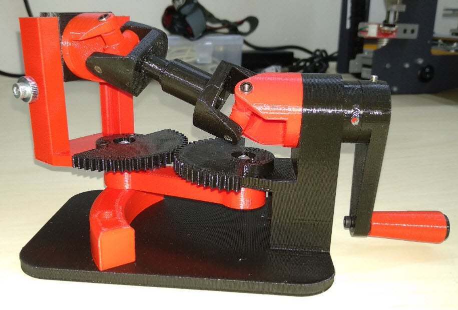
3D Printing
Mechanism in Legos
Lego makes a Universal Joint part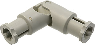
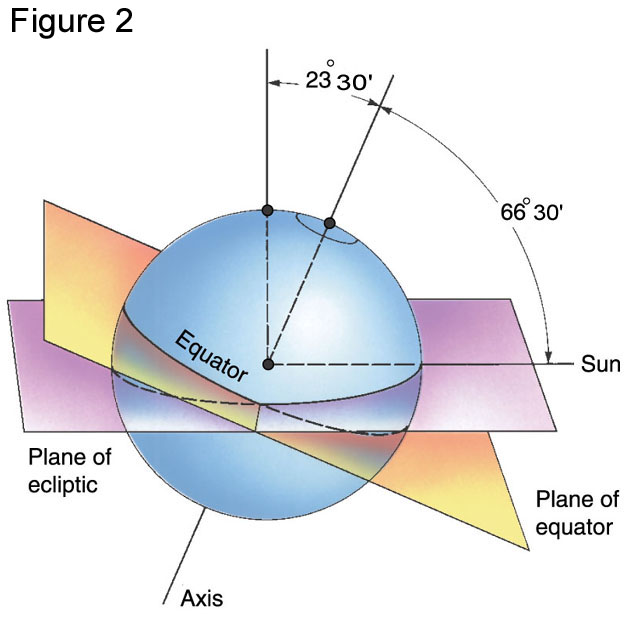
Weird Fact
In antiquity, it was noticed that the math between the two joints looks similar to the seasonal variation of day length across the year. And it is! The earth's North/South axis is angled 23 degrees from the axis of its orbit around the Sun.

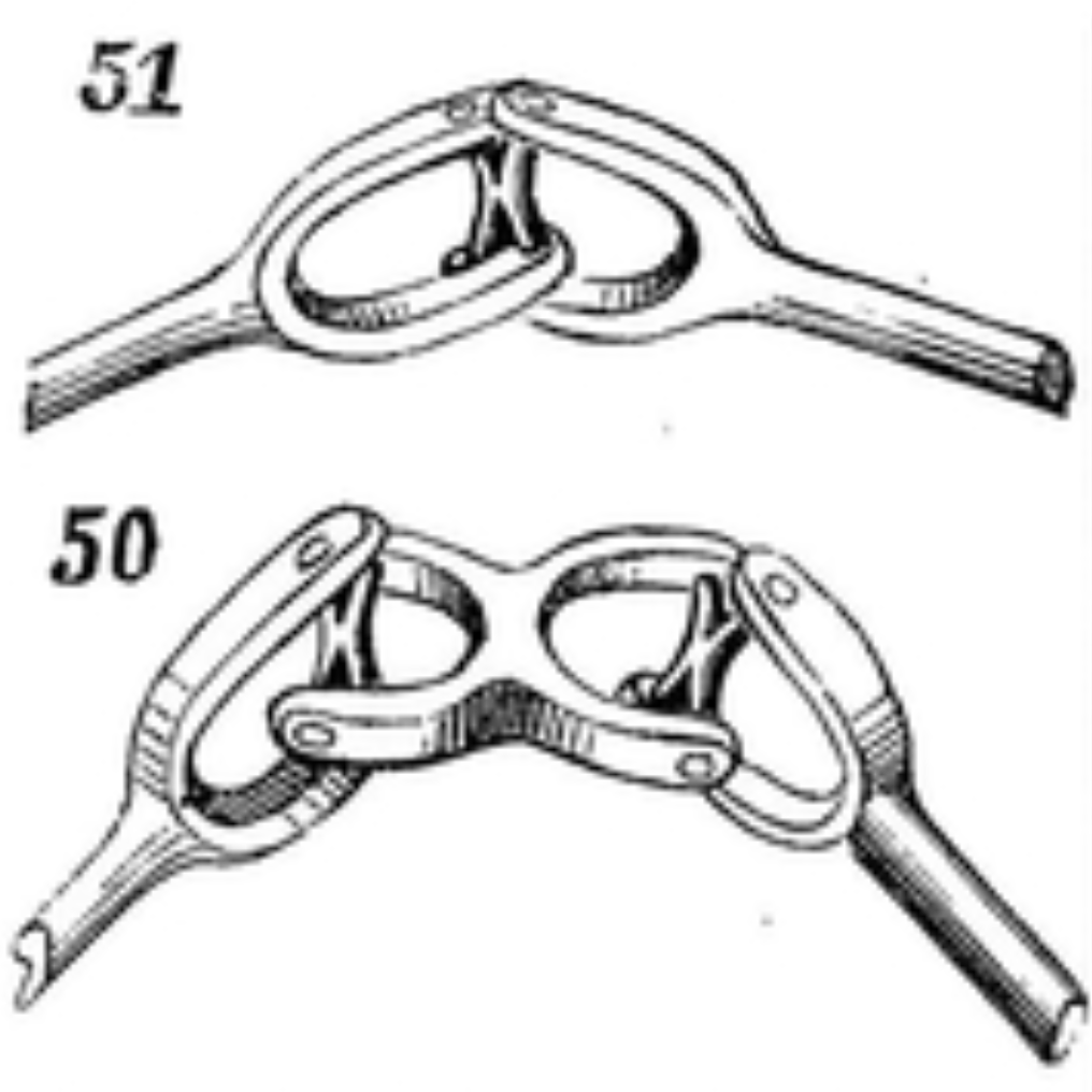
Variation: Double Universal Joint (Also known as "Double Cardan" joint)
Because of the vibrations mentioned above, a single Universal Joint is rarely used. The Double Universal Joint is very common. On vehicles, it is often simply two universal joints separated by a intermediate shaft. The three shafts can be in a "W" or "Z" shape, but the angles for both joints must be the same to avoid wobble.
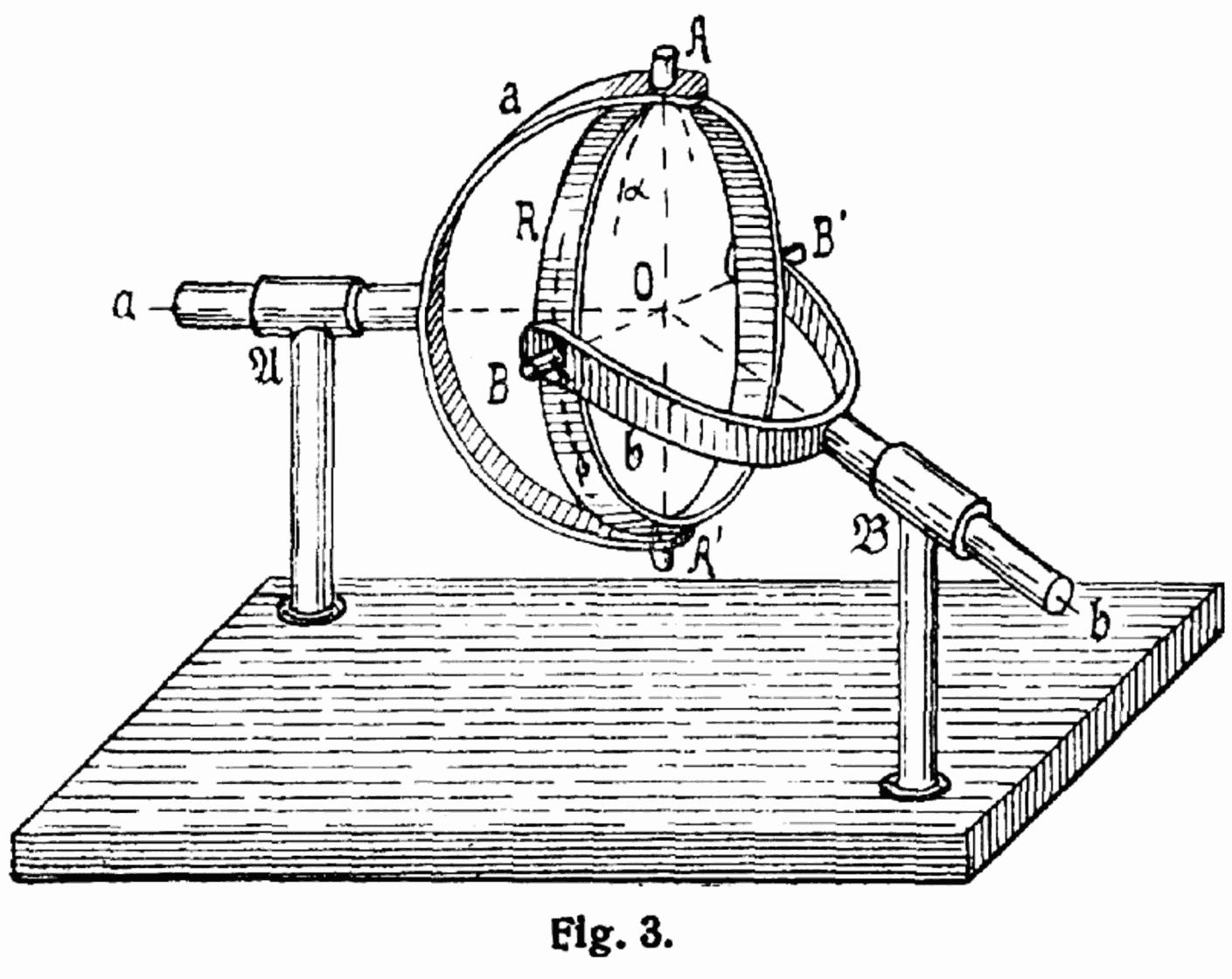
History
The universal joint idea has been around since antiquity, and been discovered or documented multiple times, for example by Gerolamo Cardano, in the 16th century and Robert Hooke, in the 17th century.
Historical notes on P1 - Hook's joint/universal joint/Cardan joint by Daina Taimina
Math
The rotational speed of the follower shaft will vary based on the angle. This can be calculated.

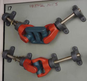
Reconstructing the Library Display
The Mechanical Library Universal Joint display is composed of
- Custom Components
- (4) 3D printable 'yoke' component
- (1) 3D printable 'double yoke' component
- (1) 1/2" plywood panel (400mm x 400mm)
- (1) 3D printed adapter for GA12 shaft to 6mm shaft
- (1) 3D printed adapter for GA12 to Gobilda U channel
- Contact us for details and files
- Mechanical Components
- (3) Valucraft U-Joint 1-0153VC (or compatible automotive U Joint)
- (1) GA12-N20 Geared Mini DC Motor
- (1) 6v Power supply
- Display Structure
- (4) Gobilda 2101 Series Stainless Steel D-Shaft (6mm Diameter, 100mm Length)
- (8) 1-Side, 2-Post Pillow Block (6mm Bore)
- (16) 1501 Series M4 x 0.7mm Standoff (6mm OD, 40mm Length)
- (20) M4 machine Screws 18mm Length
- (16) M4 Threaded Rod (10mm or cut short pieces)
- (3) 8mm Pitch Plastic Chain
- (4) 8mm Pitch Steel Set-Screw Sprocket (6mm D-Bore, 10 Tooth)
- (2) Stainless Steel D-Shaft (6mm Diameter, 40mm Length)
- (3) U-Channel (1 Hole, 48mm Length)
- (4) Flanged Ball Bearing (6mm)
Research
- Universal Joint on Cornell University KMODDL (from Clark Collection)