#000 Universal Joint
Jump to Definition Key Facts Engineering Rules of Thumb View in 3D 3D Walkthrough Mechanical Library Display Images Videos 3D Printing Lego Weird Fact Variation: Double Cardan History Math Library Research Related Mechanisms
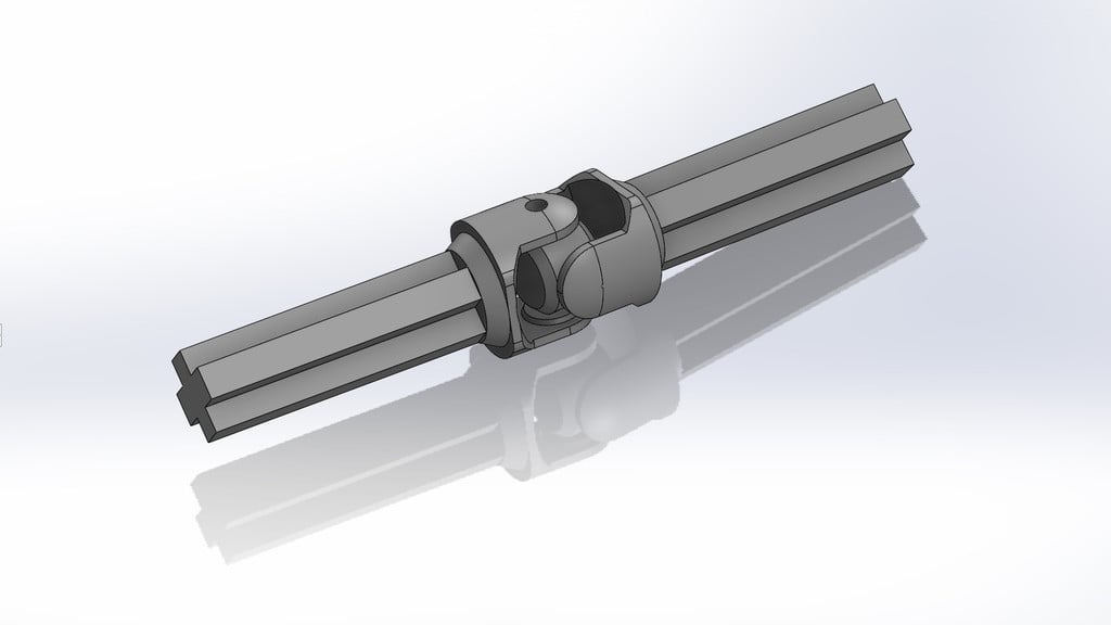
Definition

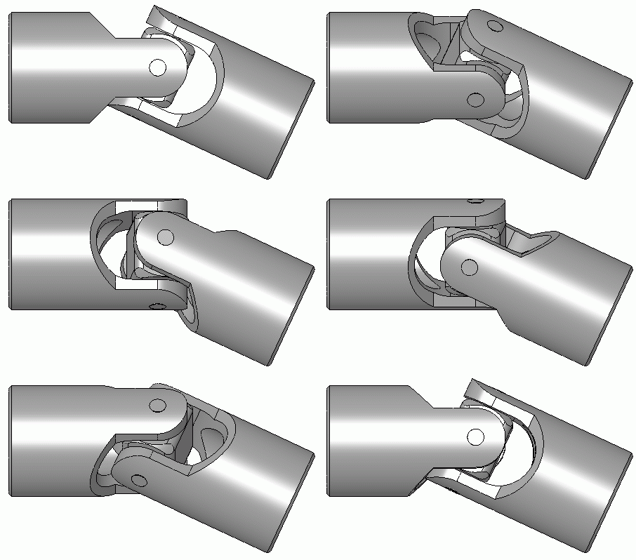
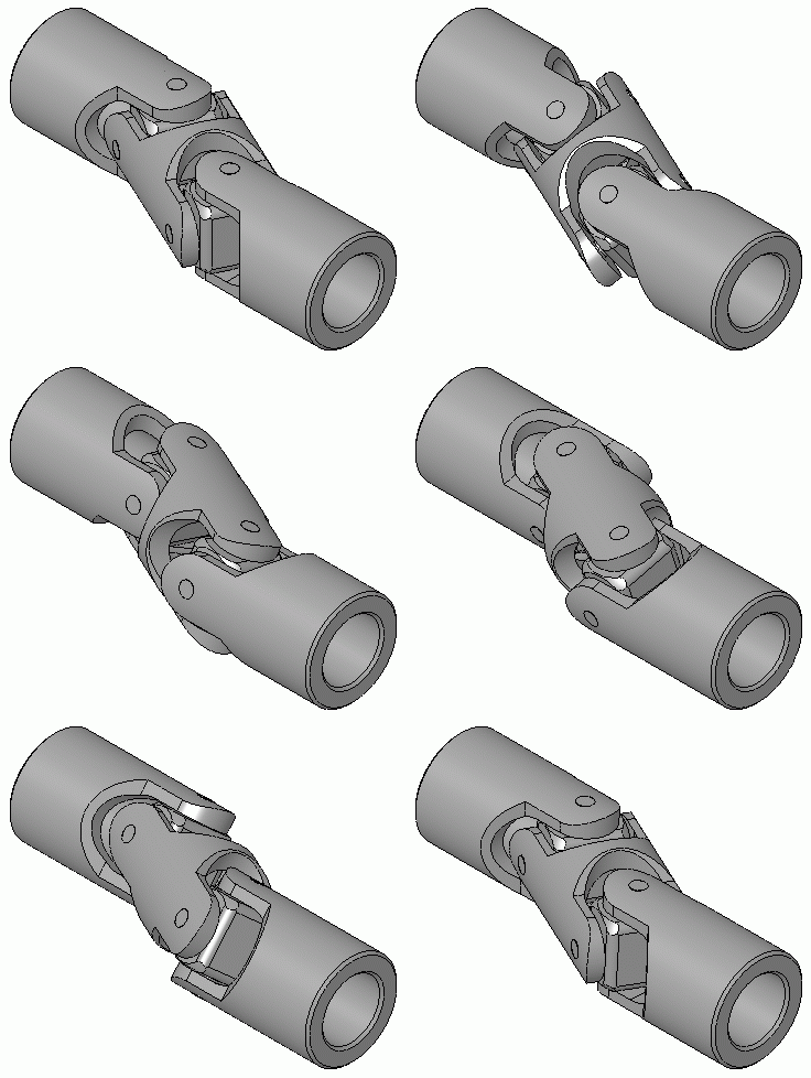
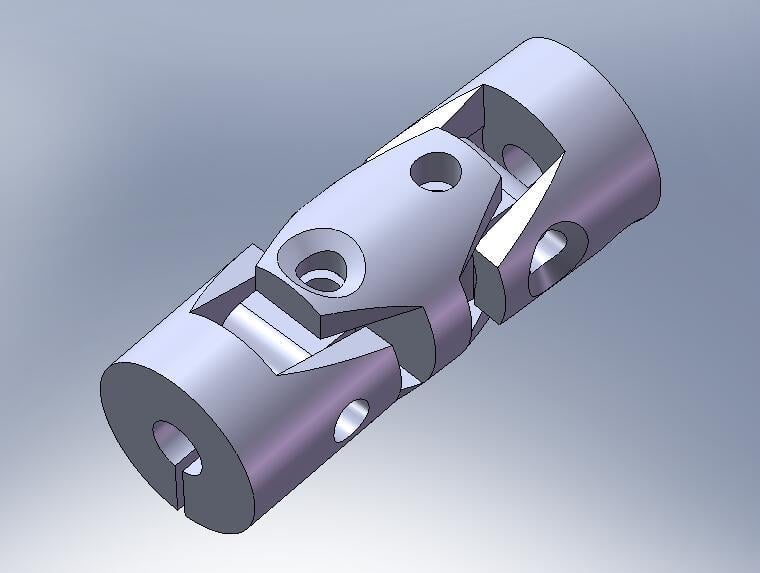
A universal joint (U-joint) is a mechanical joint connecting shafts to transmit rotary motion. It consists of a pair of hinges located close together, oriented at 90° to each other, connected by a cross shaft.

Key Facts

  • The rotational velocity of the output shaft is not constant. It will speed up and slow down during a rotation, causing wobble. The greater the angle, the bigger the wobble.
  • You can eliminate the wobble by putting 2 universal joints together, also known as a “Double Cardan Joint”.
  • There are other joints that are 'constant velocity', but are more complex (see other mechanisms)

Engineering Rules of Thumb

  • One generally wants to keep the angle below 35°, with a max angle of 45°.

View in 3D

These models use Apple "Quick Look AR" (Augmented Reality).

To use on iPhone: click link below, then click the model's image again. Hold phone over flat surface such as a table, and model should appear. One can move the phone around to inspect the model, even the insides. It can be scaled up by pinching with two finger tips, and rotated by rotating with two finger tips.

To use on Mac: click link below, then open the downloaded USDZ file in Preview app. It can be rotated by dragging the cursor.

Usage on other devices will be supported as time and resources permit.

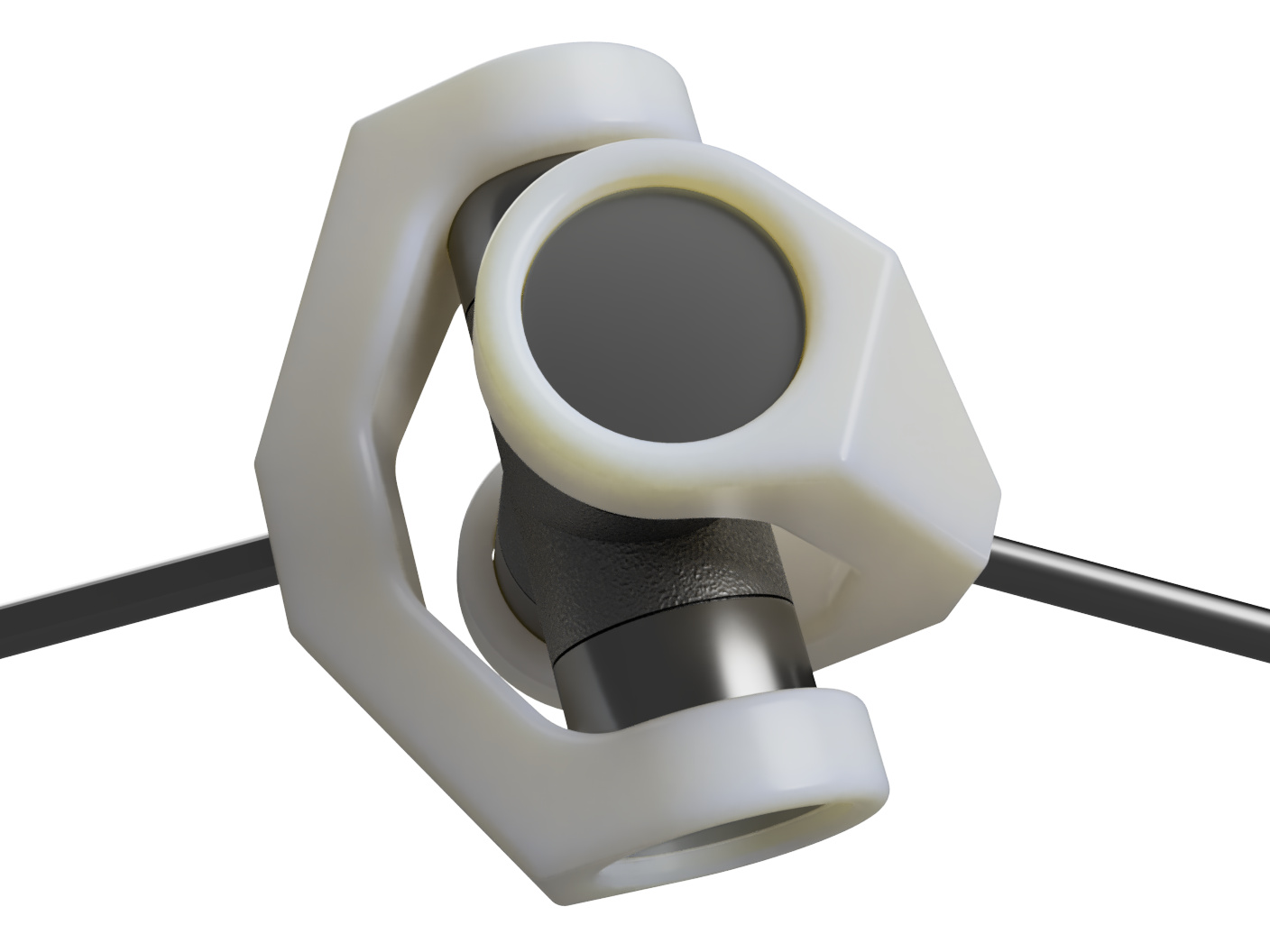
Single Universal Joint Apple Quick Look AR
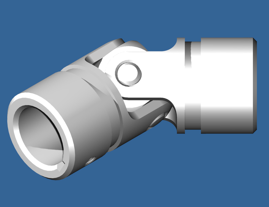
Single Universal Joint
Source:mechanical-library.org
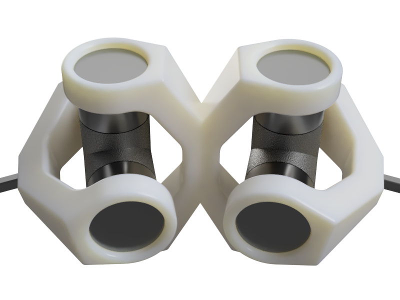
Double Universal Joint using Apple Quick Look AR
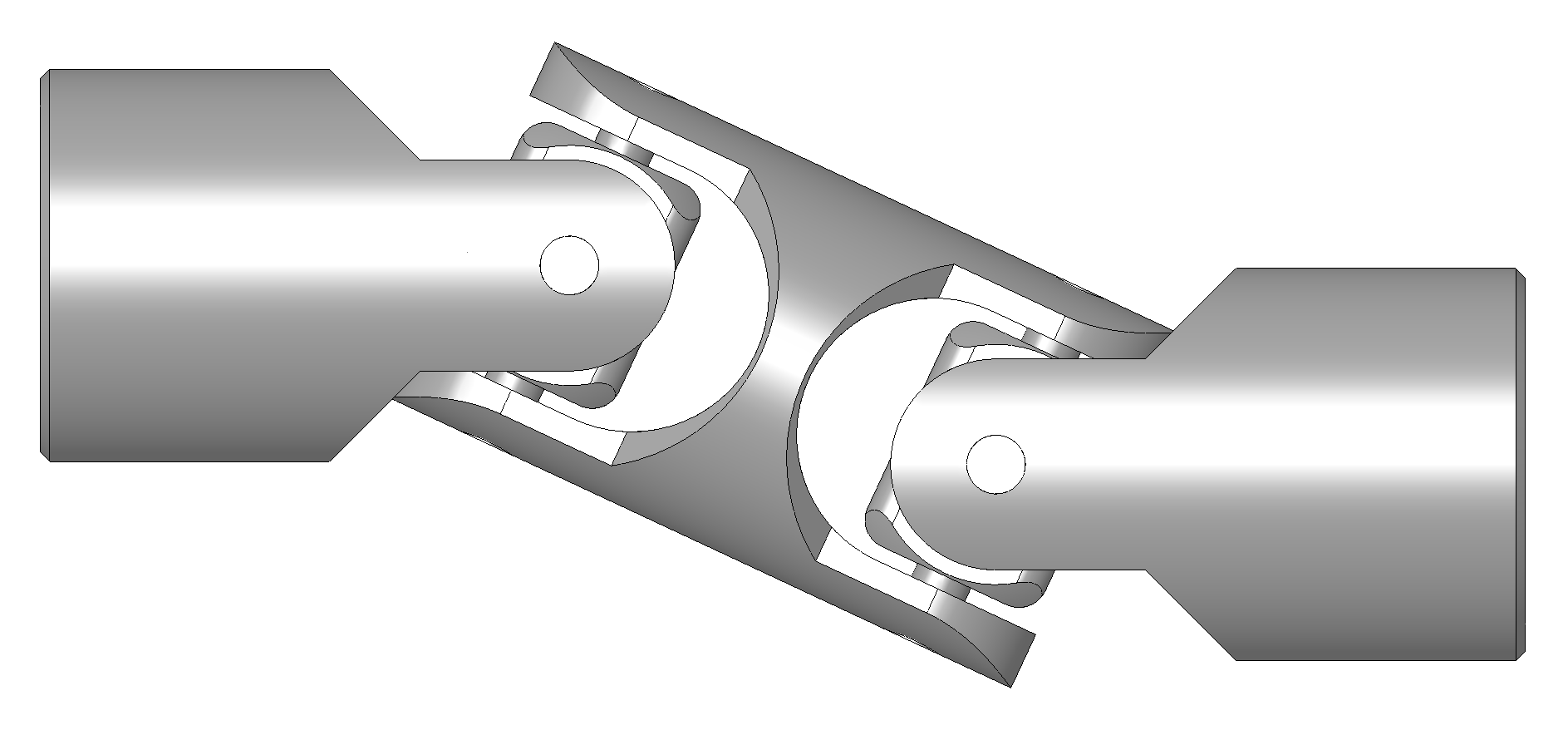
Double Universal Joint
Source:mechanical-library.org
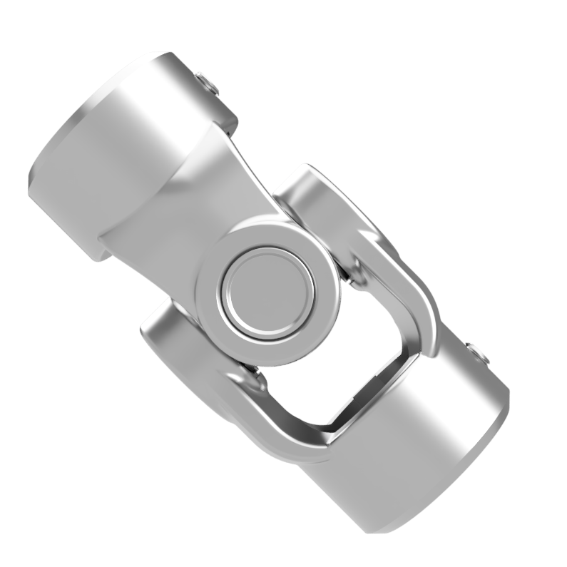
Industrial Universal Joint Apple Quick Look AR
Industrial Universal Joint
Source:mechanical-library.org

Walkthrough

A 3D walkthrough of the universal joint that can be rotated. Works best fullscreen. If on phone, use landscape mode.

Load in new window

Display

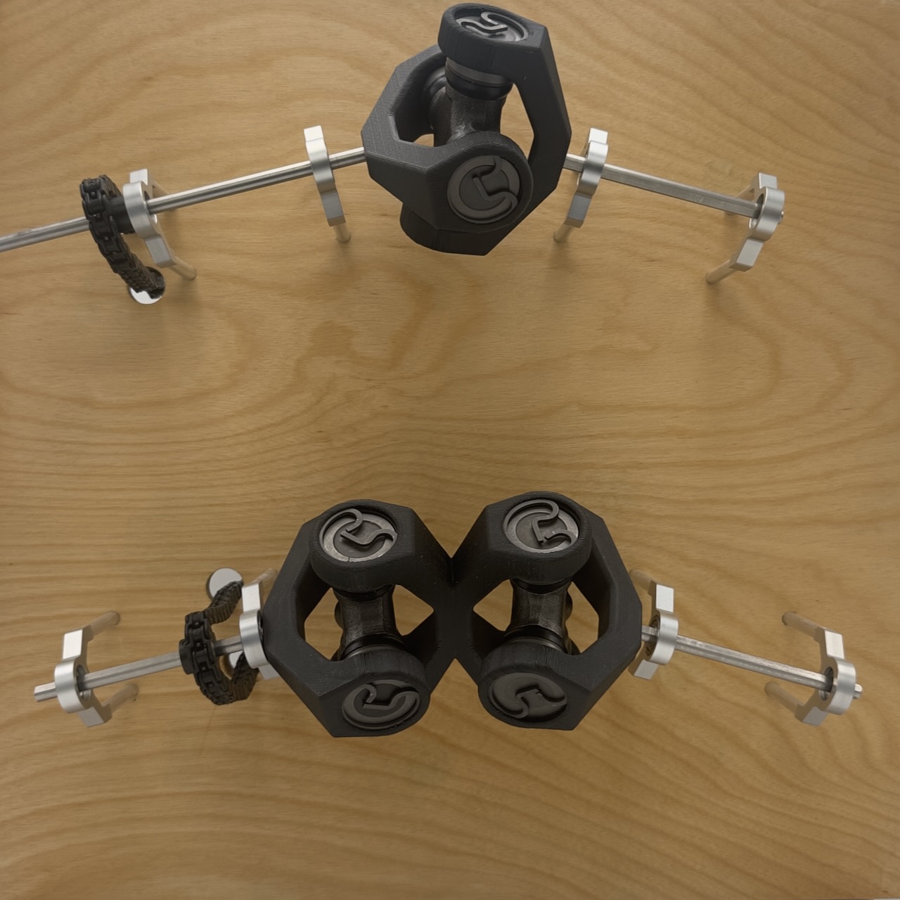
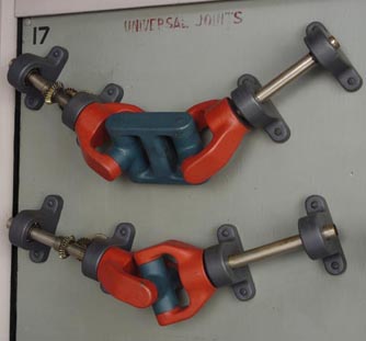
Universal Joint display in Mechanical Library
Source: mechanical-library.org
Video of Universal Joint display in Mechanical Library
Source: mechanical-library.org

Images

a universal joint 'spider', with one cap off, showing needle bearings
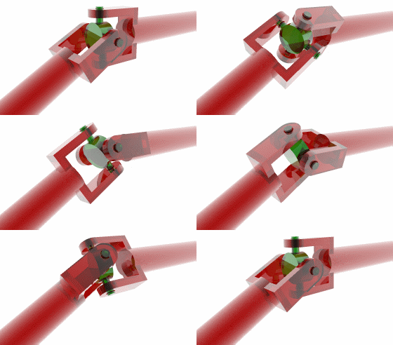
The "hub" or "spider" (green) has 4 spokes that fit into holes of the two "yokes" (red), enabling it to rotate in both directions.
a universal joint 'spider', with one cap off, showing needle bearings
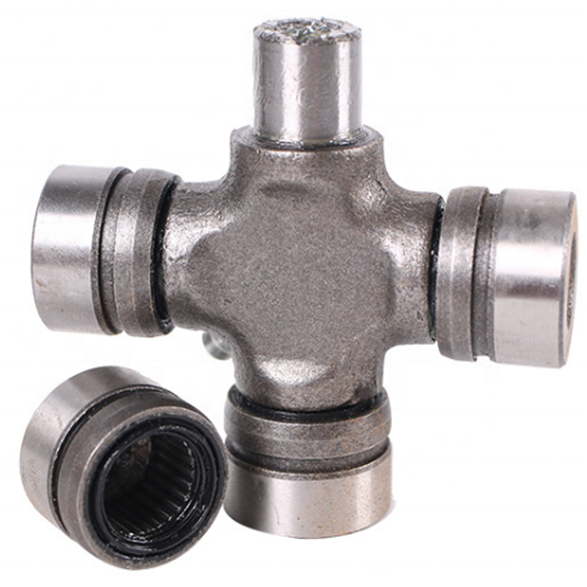
In real life use, the ends of the spokes are covered by caps holding cylinder “needle” bearings to reduce friction.
Source: mechanical-library.org
a universal joint 'spider', with one cap off, showing needle bearings
Universal joints are typically designed to protect the internal parts from dirt.
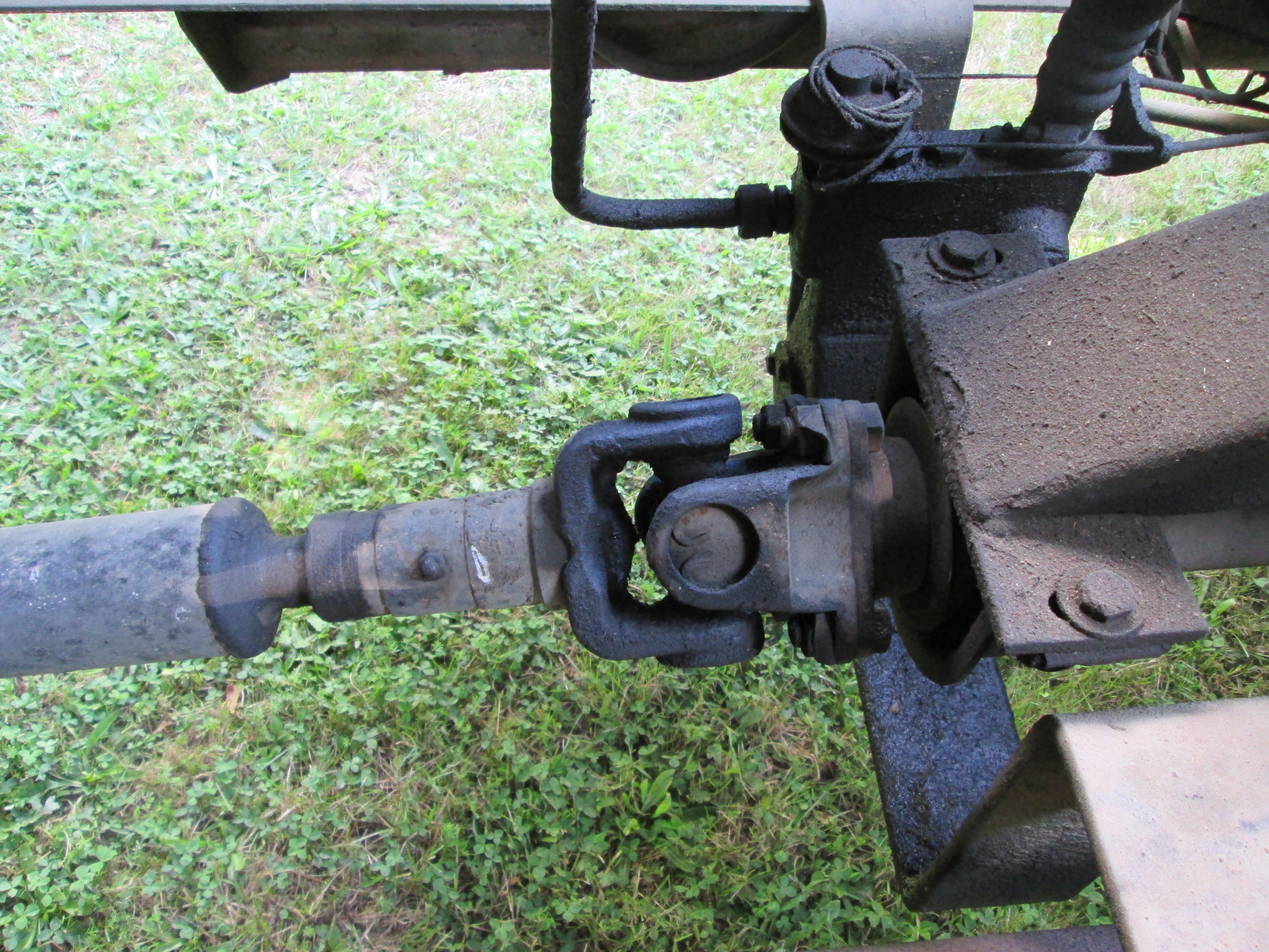
a universal joint under a schoolbus
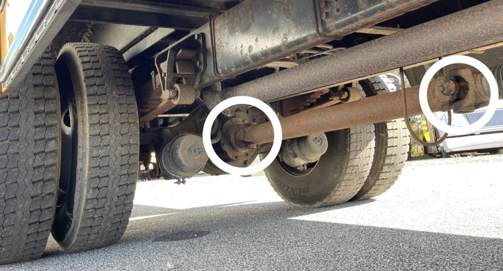
A universal joint can be seen under schoolbuses or trucks.
Source: mechanical-library.org
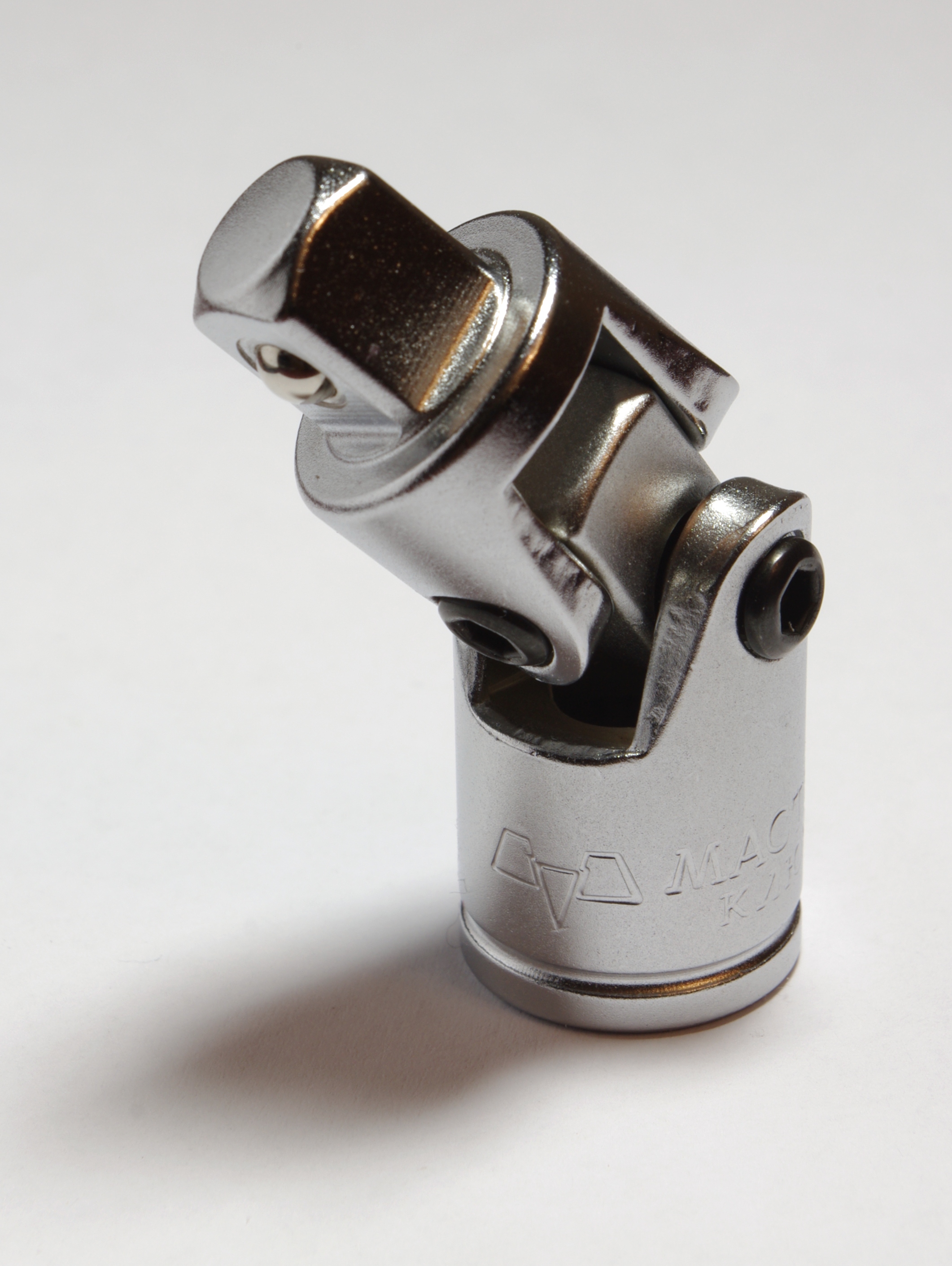
Universal Joints in a socket set attachment.
Universal Joints can also be seen in tools, like this socket set attachment.
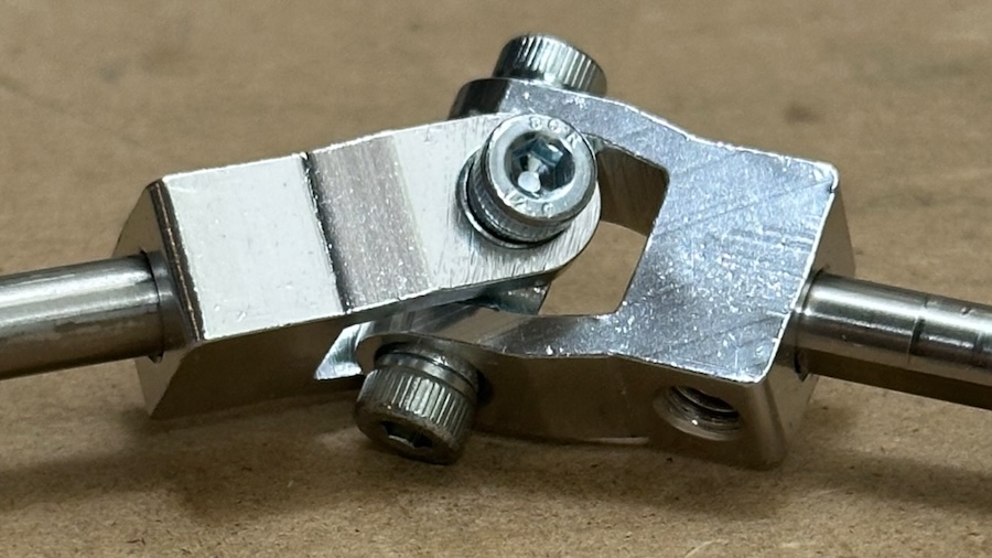
a universal joint from Gobilda
Gobila 4003 small universal joint
Source: mechanical-library.org
a universal joint in a train coupling
Universal Joints are commonly used in tough industrial environments.
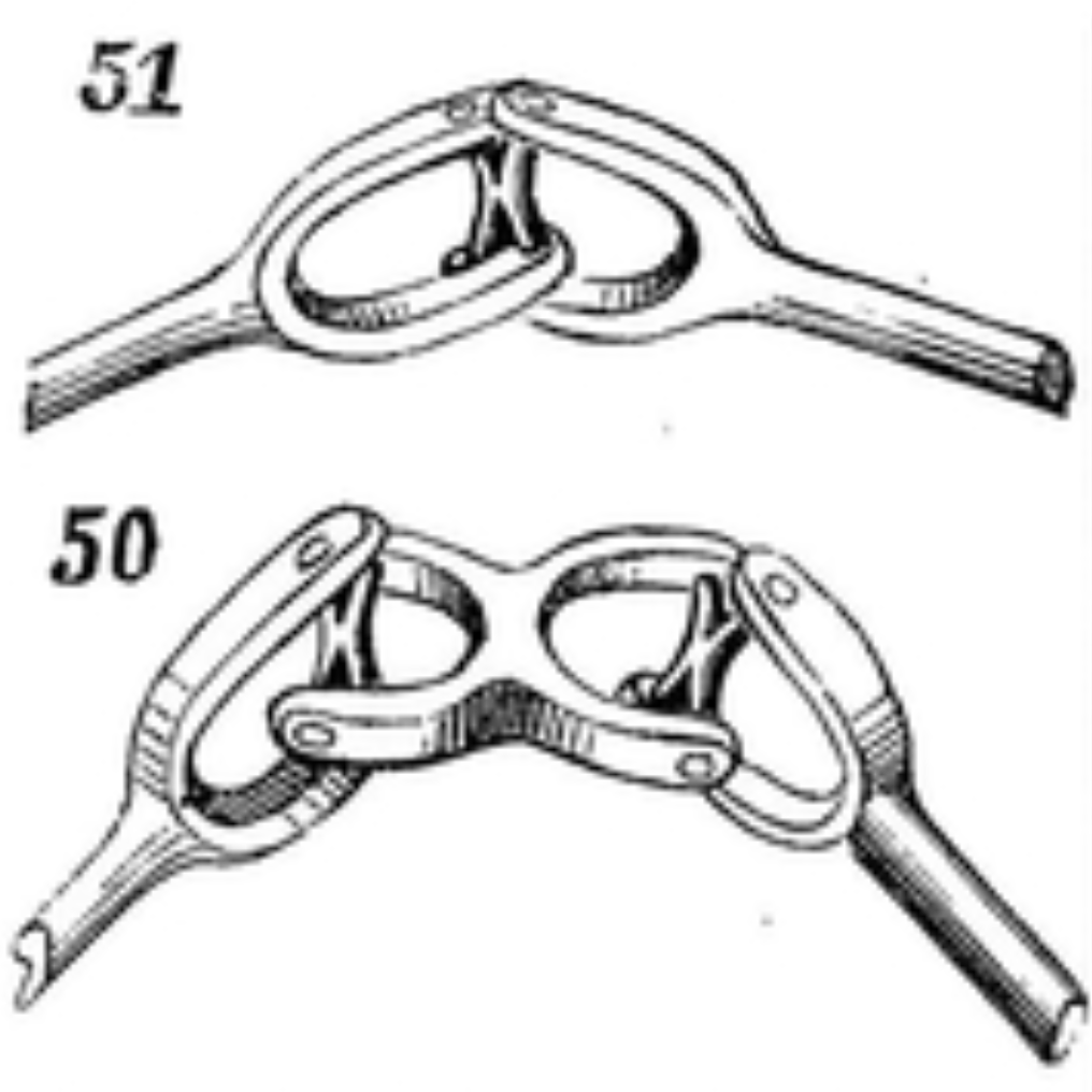
diagram of single and double universal joint
“50 and 51. Two kinds of universal joints.”
Source: Page 24, 507 Mechanical Movements by Henry T. Brown
photograph of single and double universal joint
“Singe and Double Universal Joint”
Source: Cornell University KMODDL of Clark Collection, Boston Museum of science

Videos

This video shows the parts of a universal joint, including the needle bearings
General explanation of a universal joint and demonstration of wobble of output shaft
Commercial video that shows Universal Joint in use and compares to Constant Velocity joint
Video of young mechanics showing real life universal joint repair.
Animation showing a double Cardan Joint

3D Printing

a universal joint lego piece
Lego Technic Compatible Inverse Universal Joint with 2L Axle
3D Print of Universal Joint part
Universal Joint Demonstrator
3D Print of Universal Joint
3D Print of Cardan Joint

Mechanism in Legos

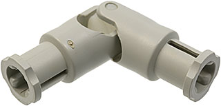
Lego makes a Universal Joint part
a universal joint 'spider', with one cap off, showing needle bearings
Lego Technic, Universal Joint 4L Item No: 9244c01
Video of 5 unusual lego universal joints

Weird Fact

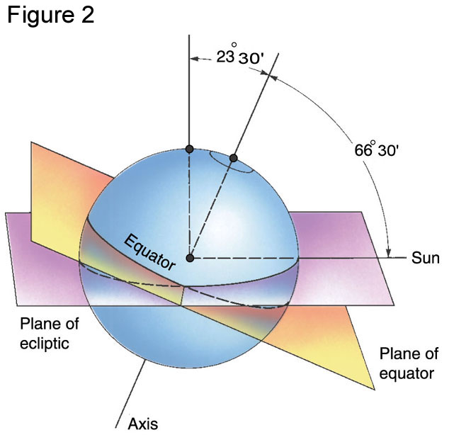
In antiquity, it was noticed that the math between the two joints looks similar as the seasonal variation of day length across the year. And it is! The earth's North/South axis is angled 23 degrees from the axis of its orbit around the Sun.
comparing the earth's rotation to the orbit of the sun
Comparing the earth's rotation to the orbit of the sun
a universal joint 'spider', with one cap off, showing needle bearings
Seasonal variation of day length

Variation: Double Universal Joint (Also known as "Double Cardan" joint)

Because of the vibrations mentioned above, a single Universal Joint is rarely used. The Double Universal Joint is very common. On vehicles, it is often simply two universal joints separated by a intermediate shaft. The three shafts can be in a "W" or "Z" shape, but the angle for both joints must be the same to avoid wobble.
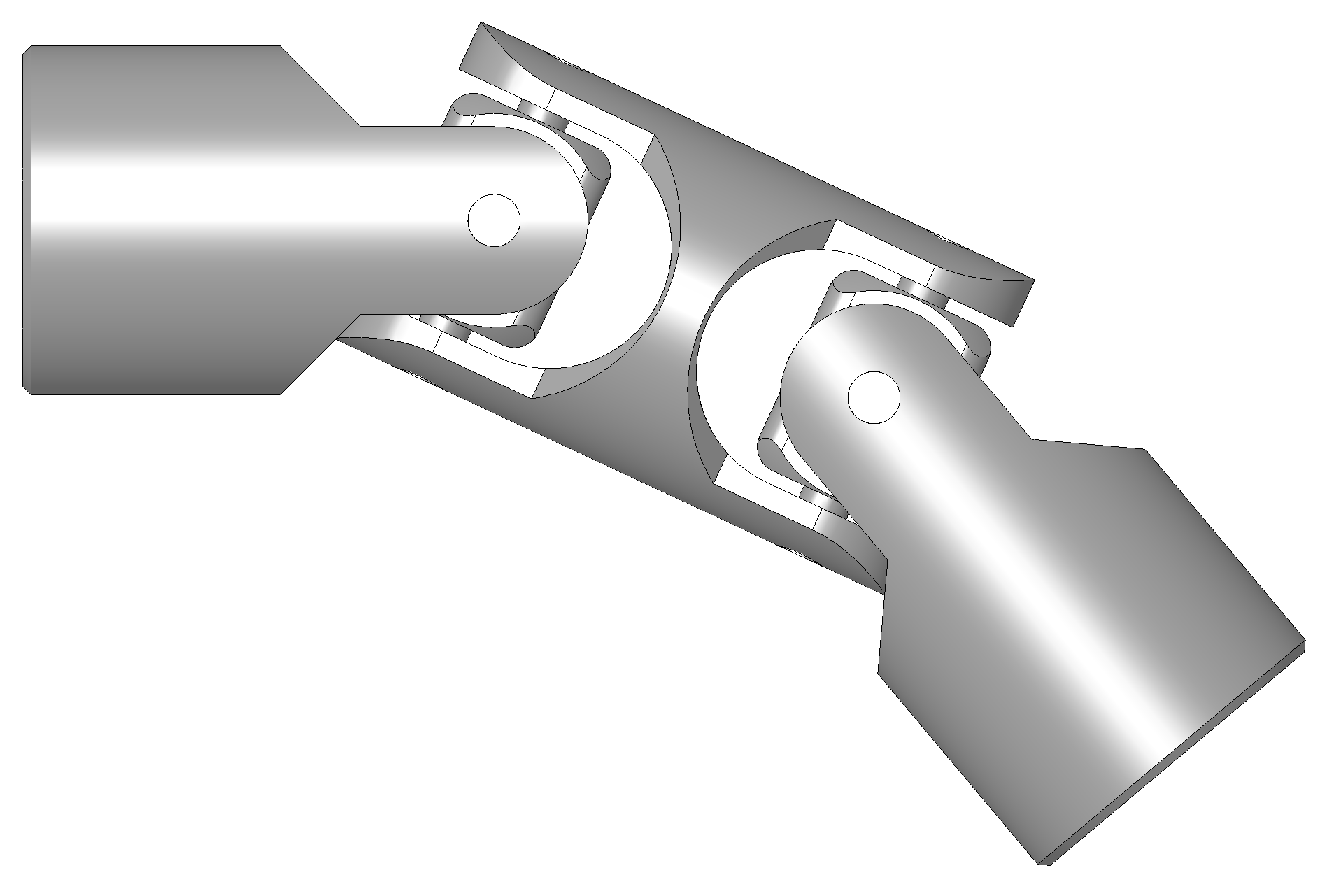
Double Cardan Joint
Source: mechanical-library.org
a universal joint 'spider', with one cap off, showing needle bearings
Double Cardan Joint
a universal joint 'spider', with one cap off, showing needle bearings
Double Cardan Joint in Z shape
a universal joint 'spider', with one cap off, showing needle bearings
Double Cardan Joint in Z shape
a universal joint 'spider', with one cap off, showing needle bearings
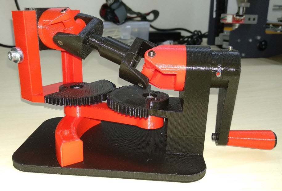
Double Cardan Joint in use, driving a worm gear
a universal joint 'spider', with one cap off, showing needle bearings
3D Print of Double Cardan Joint

History

The universal joint idea has been around since antiquity, and been discovered or documented multiple times, for example by Gerolamo Cardano, in the 16th century and Robert Hooke, in the 17th century.

Historical notes on P1 - Hook's joint/universal joint/Cardan joint by Daina Taimina
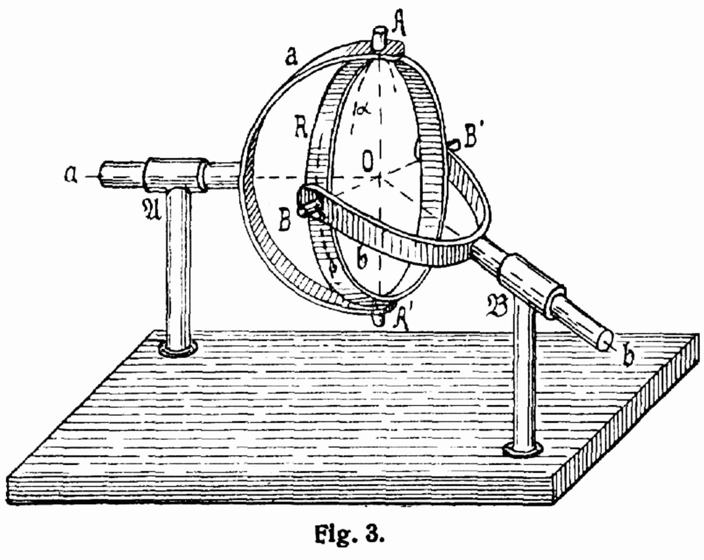
niversal Joint from Lexikon der Gesamten Technik (dictionary of technology) from 1904 by Otto Lueger
Design for simple Universal Joint from Lexikon der Gesamten Technik (dictionary of technology) from 1904 by Otto Lueger.

Math

The rotational speed of the follower shaft will vary based on the angle. This can be calculated.
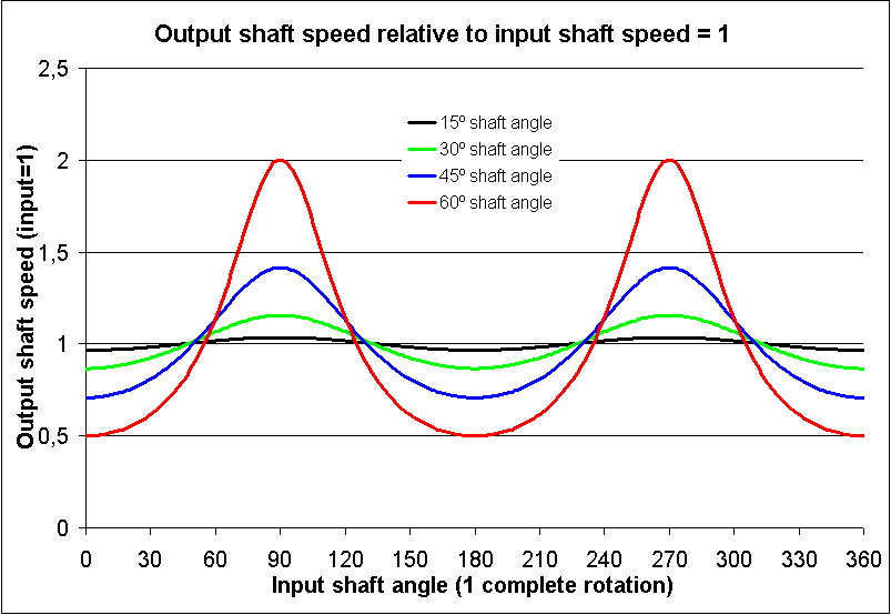
Output shaft speed relative to input shaft speed, at different angles between shafts
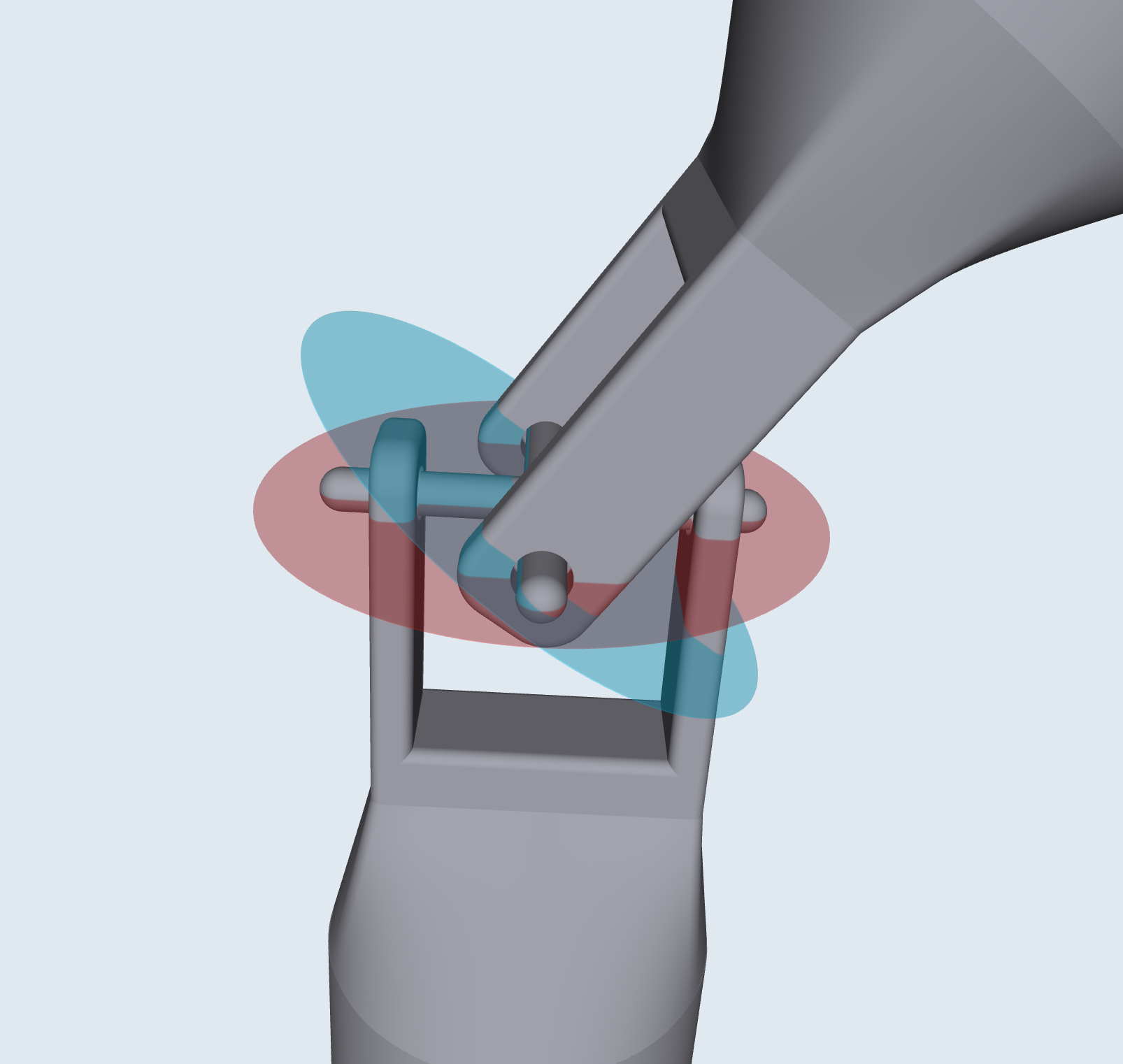
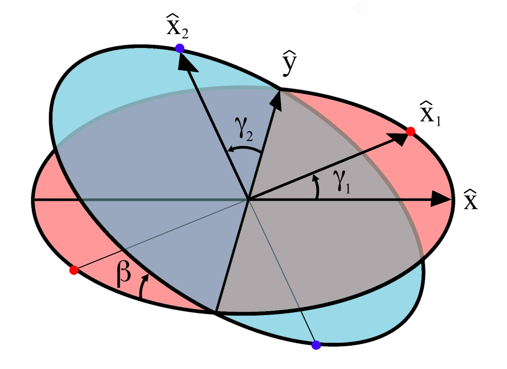
Diagram showing axis of rotation of both shafts
Chart of output shaft realative to input shaft
Diagram showing axis of rotation of both shafts
Equation of motion
Output velocity (ω2) = input velocity (ω2)* (cosine (β) / (1- sin²(β) * cos()² γ1)) ω2 = Output velocity ω2 = Input velocity β = Angle between planes of rotation, with zero being parallel γ1 = the angle of rotation for axle 1

Reconstructing the Library Display

The Mechnical Library Universal Joint display is composed of

Research

  • #123 Constant Velocity Joint (future)
  • #245 Hobson's Joint (future)