About "Mechanical Wonderland": The Clark Collection of Mechanical Movements
Intro
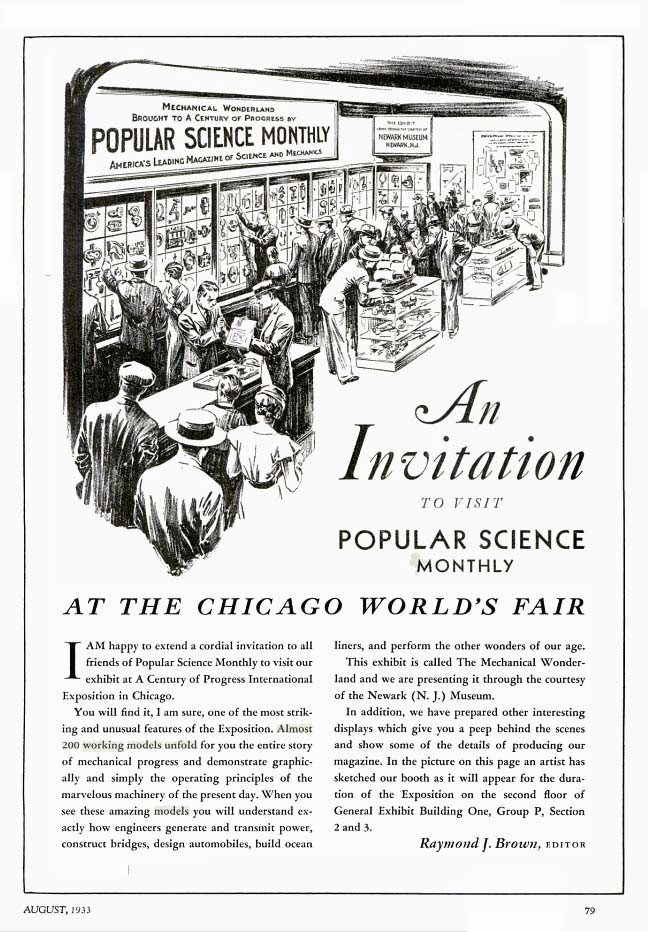
The Clark Collection of Mechanical Movements is a museum exhibit at the Museum of Science (Boston) made in the 1920s that shows over a hundred different mechanisms, including gears and models of machines. This exhibit and a copy were displayed at the Museum of Peaceful Arts, Newark Museum, and the 1934 Chicago World's Fair, titled "A Century of Progress".
This exhibit has inspired many inventors, engineers, and project, including Mechanical Library project. Sadly, it was not readily available online. This research aims to honor the creative work and to inspire new generations. The various historical photos and news clippings below depict interesting people and a fascinating time of optimism for the future, during two of the darkest periods in American history, the Civil War and Great Depression.
History
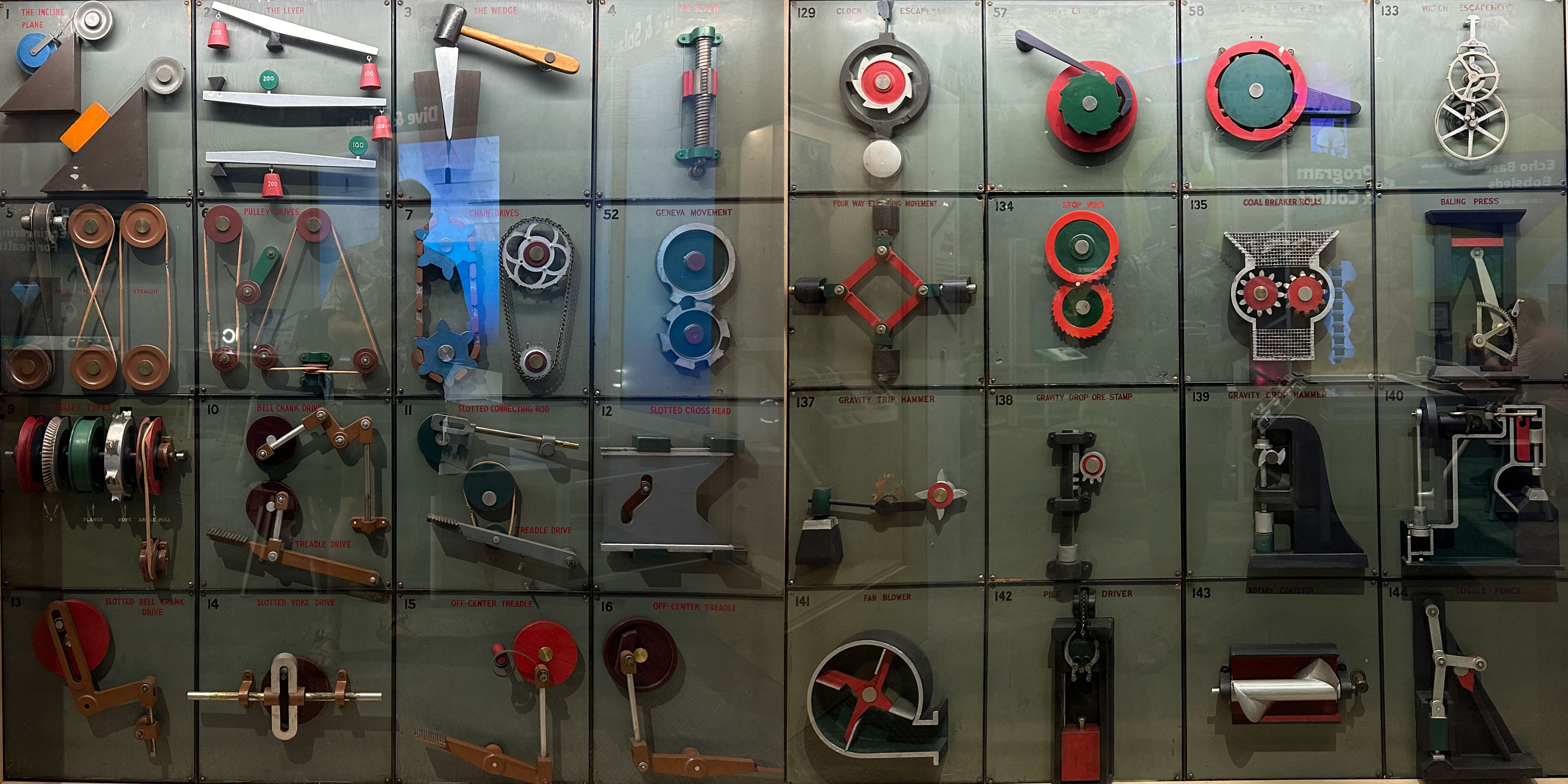
W.M. (William Milton) Clark (1862/9 -?), of South Orange, NJ, a self-described "hobbyist", "through the help of the '507 Mechanical Movements', acquired the foundation for a mechanical education, without schooling in the regular way."14 The exhibit, originally titled "Mechanical Wonderland," was made over "20 years" by Mr. Clark in the early 1900s and displayed in the Boys' Department of a New York department store.8
Inspiration
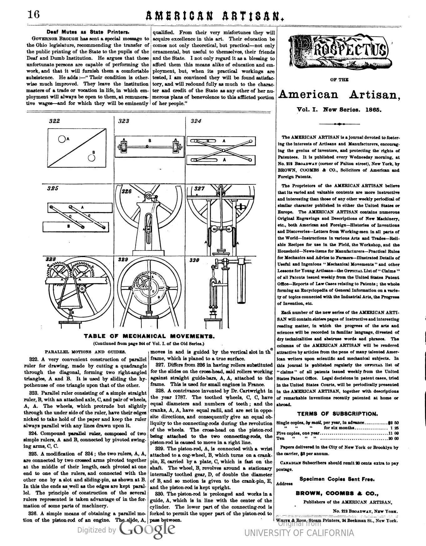
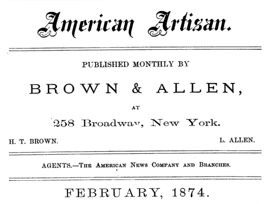
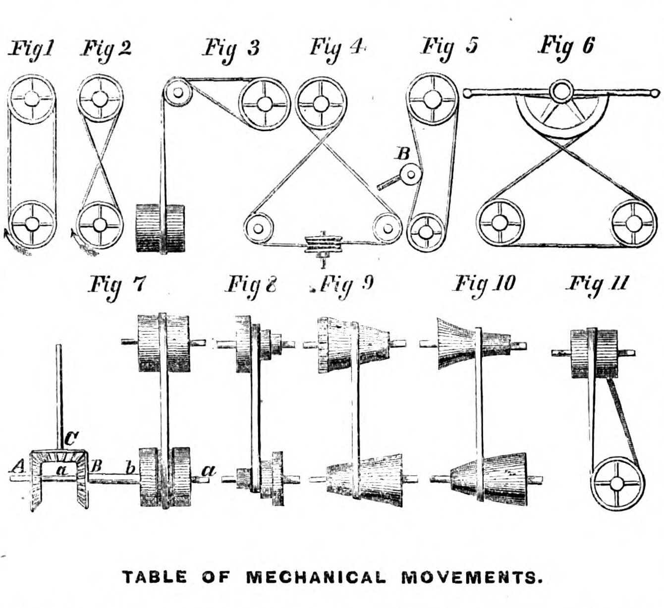
The exhibits were inspired by "illustrations and descriptions originally published in 1864 in a weekly series in the "American Artisan,"2 a weekly publication edited by Mr. Henry T. Brown, a prominent patent attorney."1 The magazine, not to be confused with later magazines with the same name, covered new inventions and patents in Civil War-era America.
In 1868, Henry T. Brown published the series as the book Five Hundred and Seven Mechanical Movements 3. This book has been widely inspirational to engineers and inventors to the present day.
Clark Collection
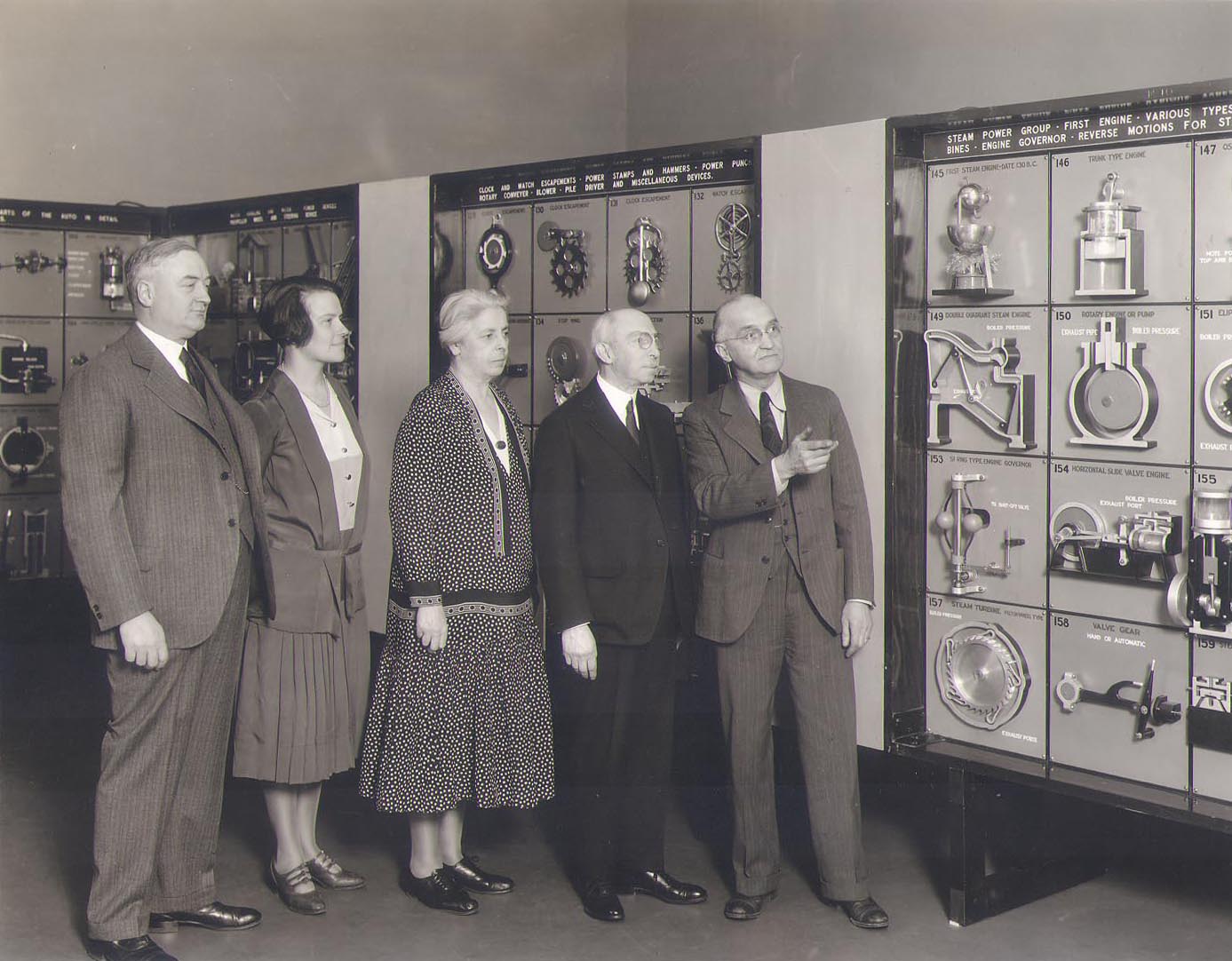
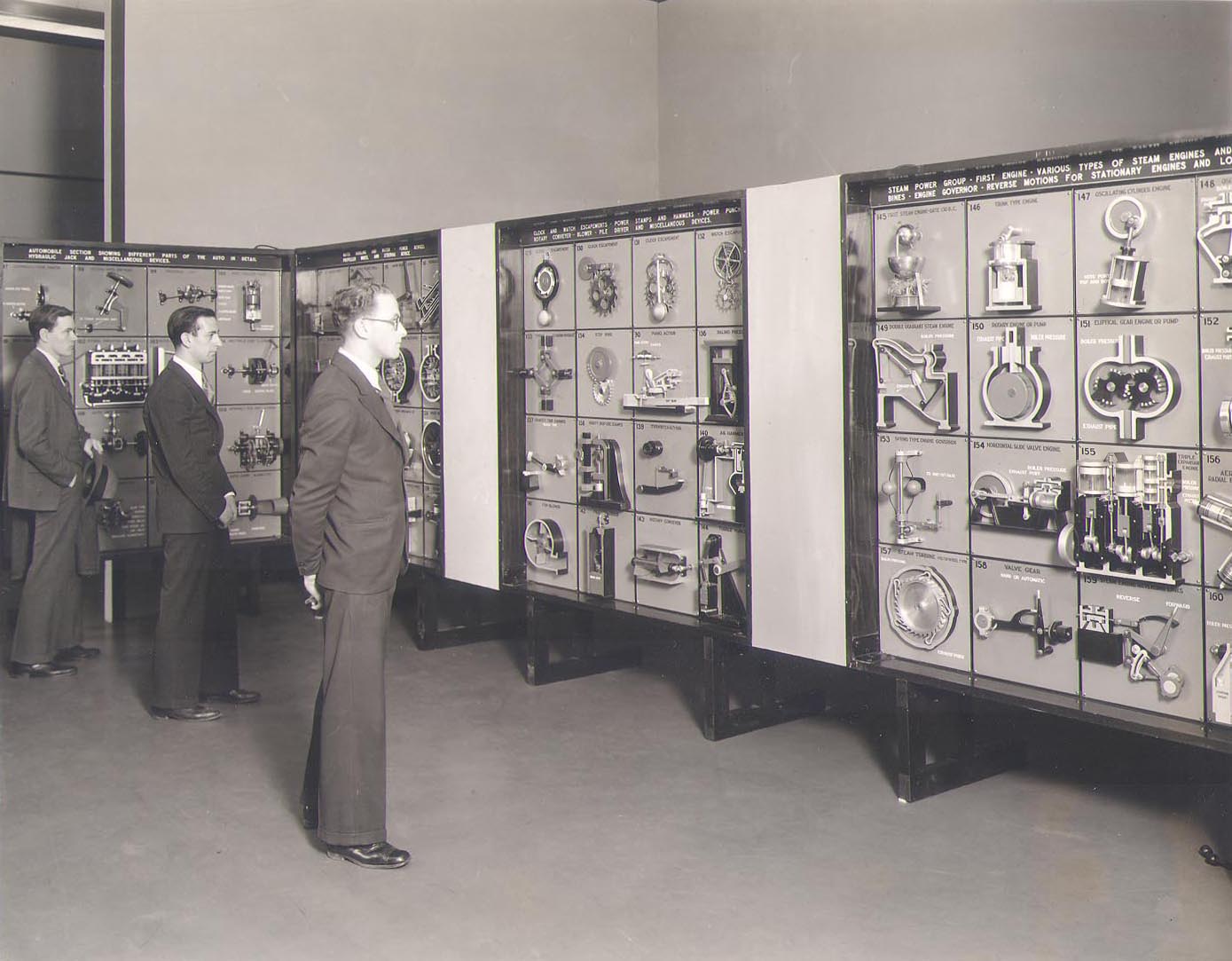
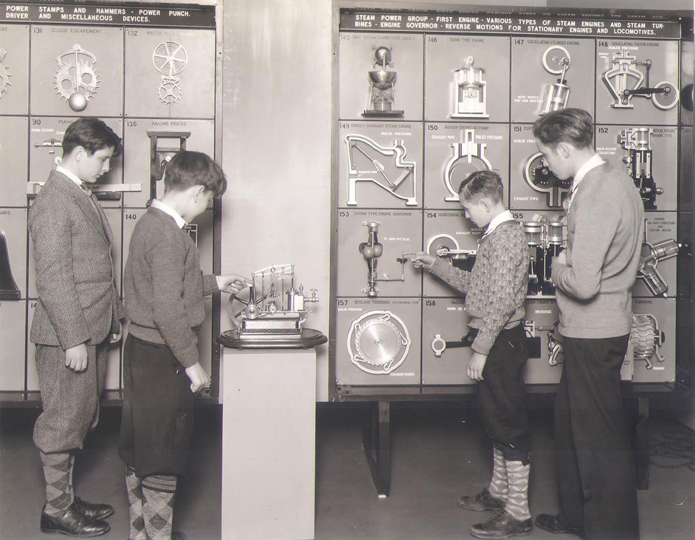
In the 1920s, over 135,000 people saw the "Mechanical Wonderland" in the Grand Central Palace in New York City in a one week period. 14 In 1928, the "Mechanical Wonderland" exhibit was displayed at the Museums of the Peaceful Arts and received press coverage5 6 7 8 9 At some point in the early 1930s, the Museum of the Peaceful Arts closed, and elements were inherited by the new New York Museum of Science and Industry 24. In the 1940s, the museum closed and at some point the Mechanical Wonderland exhibit was installed in the Museum of Science, Boston under the name the Clark Collection of Mechanical Movements.
Newark Collection
In the late 1920s, John Cotton Dana, the founder and first director of the Newark Museum in New Jersey, expressed interest in collecting the exhibit. Dana led the Newark Museum to expand its collection to include contemporary American commercial products as folk art as well as factory-made products. Dana was quoted as saying, “A great department store, easily reached, open at all hours, is more like a good museum of art than any of the museums we have yet established”.22
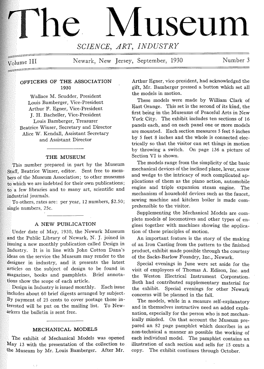
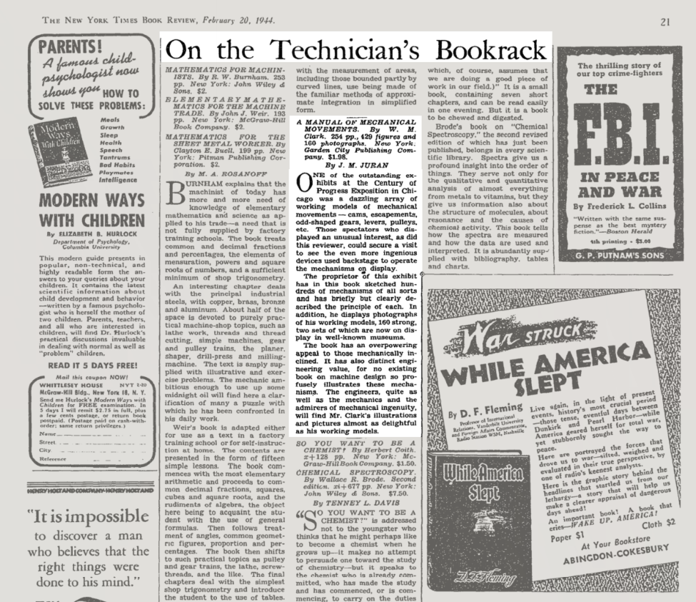
In 1930, a second exhibit was constructed by W.M. Clark and donated to the Newark Museum by Louis Bamberger. The museum displayed a collection of 160 models of mechanical contrivances which demonstrate 200 standard movements upon which modern industry is founded.16
In 1934, Newark Museum collection of "Mechanical Wonderland" exhibited in the Chicago World's Fair, 'A Century of Progress' and returned to Newark Museum. In 1937, Newark Museum collection was exhibited at the Massachusetts Institute of Technology during the Annual Meeting of the Society for the Promotion of Engineering Education and later returned to Newark Museum. In 1954, The Newark Museum published a review of the exhibit.16 At some later time, The Newark Museum of Art placed the collection in storage, where it remains.21
The Interactive Mechanical Wonderland Exhibit
This collects, for the first time, the photos of the Boston Museum of Science Clark Collection, by way of Cornell University KMODDL17, with photos and museum exhibit texts from Newark Museum publications16. This information and files are collected here for the convenience of future readers, no copyright claim is implied.
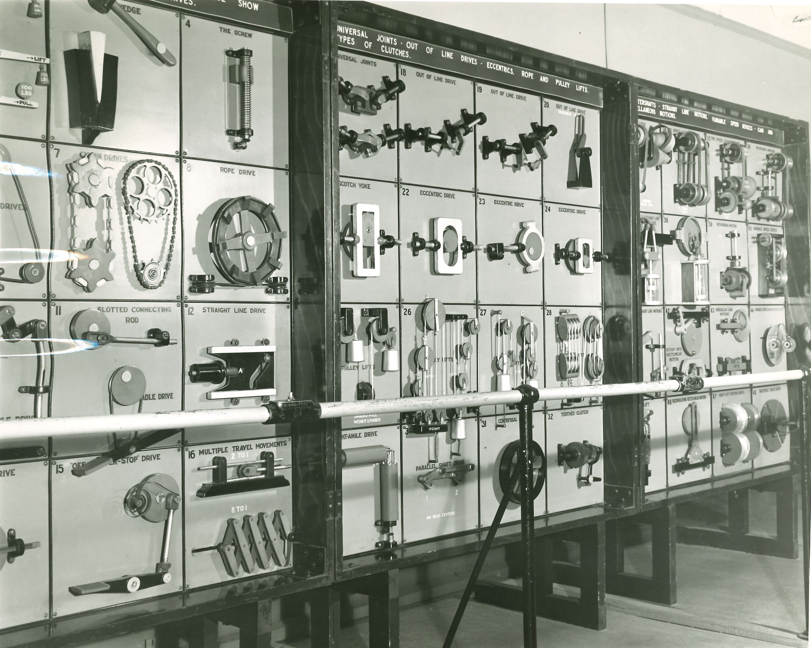
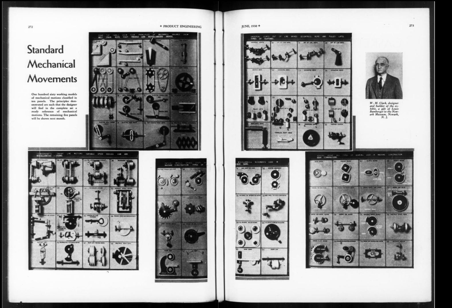
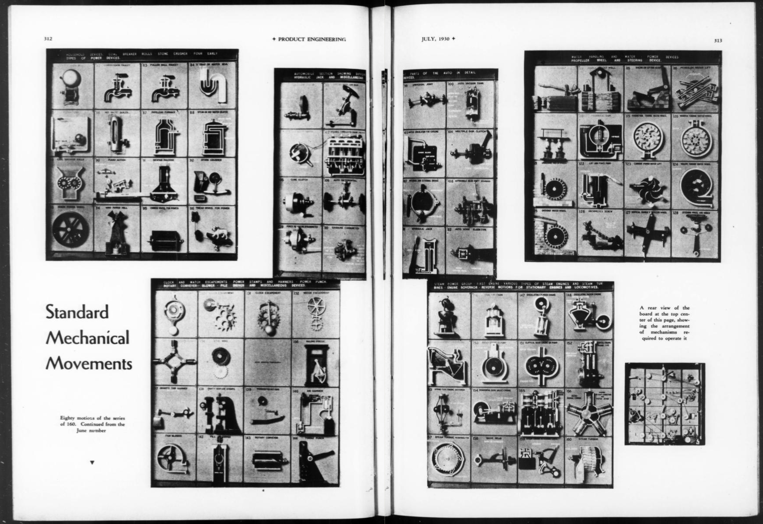
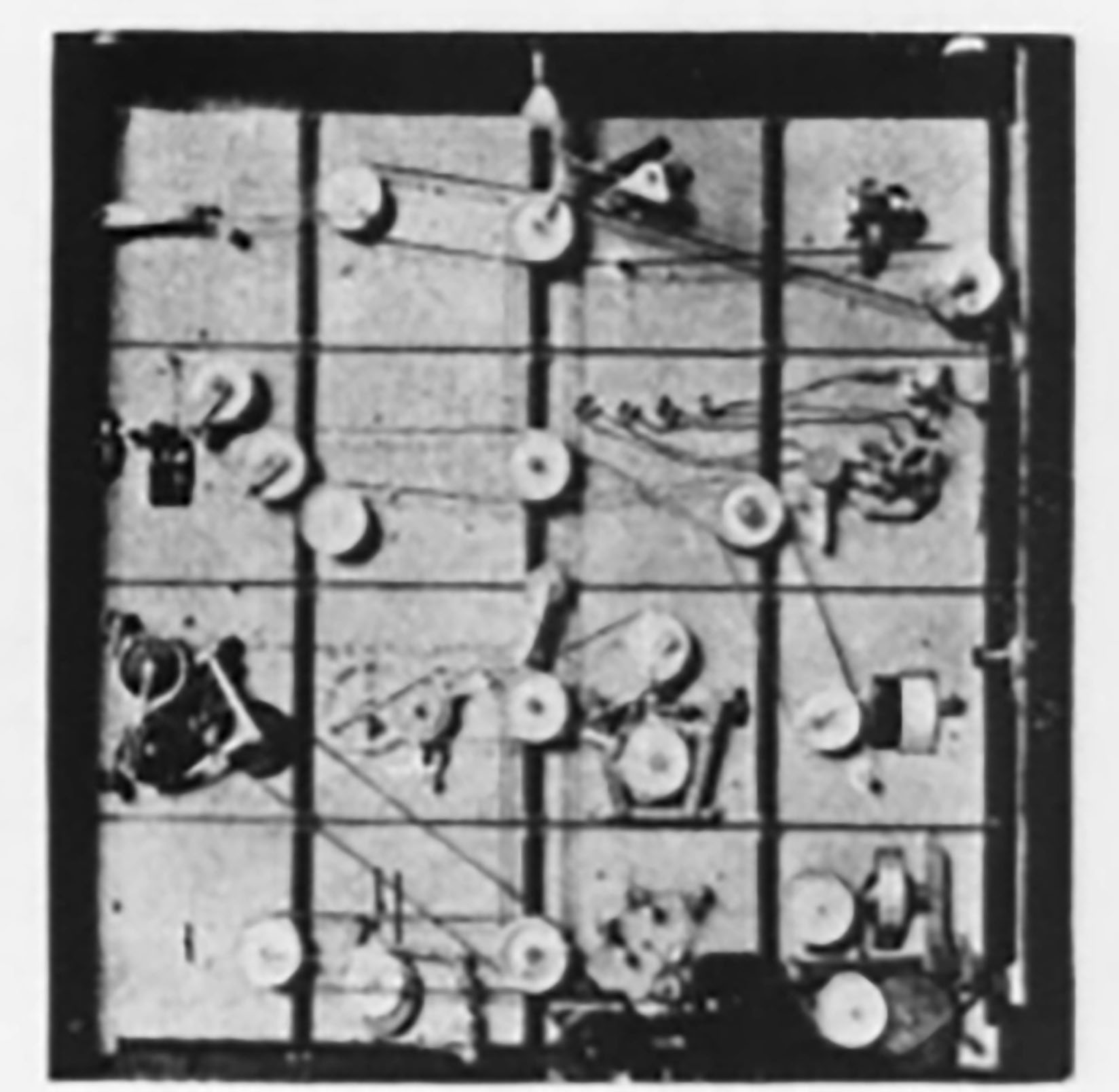
The original exhibit consisted of ten sections, each with 16 square panels of mechanical movements or devices. Each individual panel is connected electrically so that the visitor could set a section in motion by pressing a button. The exhibit sections each measure 5 feet 6 inches square, and weigh from 475 to 550 pounds apiece. In each section are sixteen small panels 15¼ inches square, each containing one or more movements. "The exhibit could be set up or taken down in a few hours."
Click each photo to see original exhibit text from the Newark Museum8.
Section I Nos. 1-16, Four principles of mechanics, Belt, chain, rope, foot treadle and miscellaneous drives.
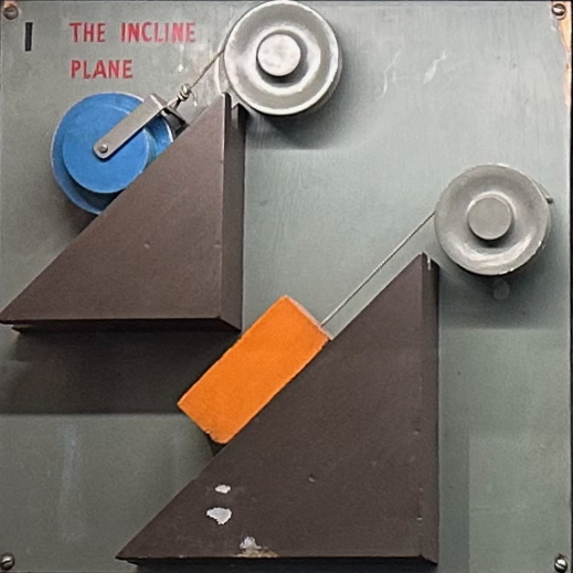
1. Inclined Plane. The inclined plane is one of the basic principles of modern machinery. Its chief purpose is to enable a small force to overcome a large force. The act of rolling a barrel up a plank into a wagon is a simple example of the use of the inclined plane. Modifications of this principle are the wedge and screw.
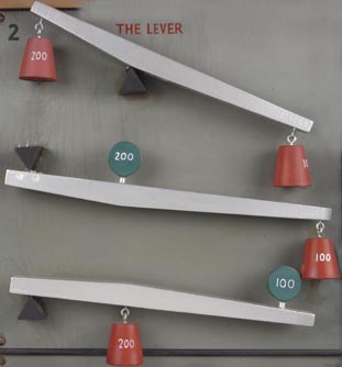
2. Lever. The lever is another basic principle of mechanics. It consists of a rigid bar resting upon a point called the fulcrum. The points are arranged in model 1 as in pliers and shears, model 2 as in a shovel, model 3 as in the wheelbarrow. The wheel and axle, and pulley are modifications of a lever.
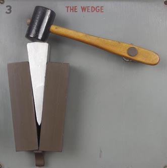
3. Wedge. The wedge is one of the oldest mechanisms and comes under the heading of the inclined plane. Some examples of wedges are the ax, chisel, nails, pins, carpenter's plane and cutting tools of nearly all kinds.
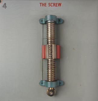
4. Screw. From the point of view of the mechanic, the screw is simply an inclined plane wrapped around a cylinder. The vise and letter-press are examples of the screw whose purpose is to obtain increased pressure. Another example, the jackscrew, is used by builders to lift heavy objects with the least effort. The propellers of boats and airplanes are further examples.
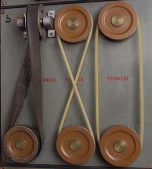
5. Belt Drives. Machines are of two kinds the driving and the driven. Some driving machines are steam and oil engines, electric motors, and water wheels. Examples of driven machines are lathes, drills, planes, and saws. Some connecting link or means of transmission between the two is necessary. A common method is to use belts, chains or cogwheels. By twisting a flat belt half way the shafts may be driven at right angles if the belt rotates as indicated in this specific arrangement. In order to make belt track, center of upper pulley must be in line with right edge of lower pulley. In model 2 reversed motion is obtained by giving the round belt a half turn; and model 3 shows belt in straight line drive with pulleys rotating in same direction.
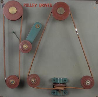
6. Belt Drives. Left hand model shows method of keeping loose belt taut at all times. Other model shows method of transmitting power by round belt in different planes producing the same rotation on the two lower vertical pulleys as indicated by arrows.
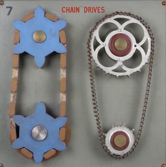
7. Chain drives. This panel shows early and modern forms of chain drive, the later type on the right being the universally used chain. It is called the silent chain and has small rollers at the contact points, making an almost frictionless performance. The speed of the sprocket wheels is inversely proportional to the number of teeth. Therefore model 1 shows a speed ratio of I to l and model 2 a ratio of 2 to 1.
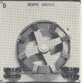
8. Rope drive. Form of pulley used for transmitting power by rope drive, having grooves to prevent slipping and to make it a positive drive. The two smaller pulleys below are guide pulleys. Such a drive is used for long distance transmission-example: obtaining power in various sections of an oil field.
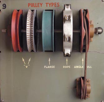
9. Pulley types. Pulleys are of two kinds, fixed and movable. Both are combined for practical work. These are all fixed pulleys which consist of a wheel with grooved rim, called a sheave, free to rotate on an axle which is supported in a fixed block. A flexible rope or cable passes over the wheels and these types show variations in rim to keep the belt from slipping off. The fourth pulley from the left is essentially for a round belt or rope, and because pulley 5 kinks the rope or belt, it is possible to get the greatest pulling power without slipping.
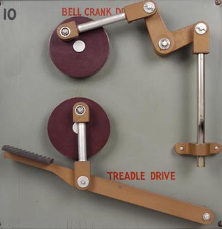
10. Treadle drive. Treadle drive derived its name from the foot method of obtaining power. The force applied to the treadle is transmitted
by the pitman or connecting rod into rotary motion by crank or disk.
Bell crank drive. This device makes use of an elbow shaped lever. It is a convenience for transmitting power in different planes
as desired.
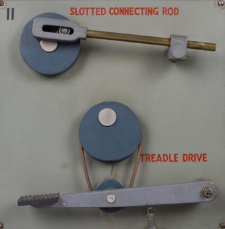
11. Slotted connecting rod. Rotating disk gives motion to rod with pause at both ends of stroke. This is used on brick making machinery. The
pause allows mold to be loaded and unloaded at each end of stroke.
Treadle drive. This treadle drive dispenses with wrist pin used in No. 10 and uses a belt and eccentric or off center pulley.
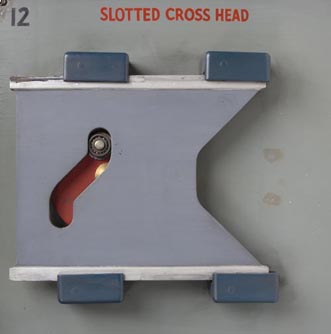
12. Straight line drive. The straight line motion of A is converted into rotary motion by action of crank B working in an S shaped slot. This device does away with oscillating motion of rod as in No. 11 (upper).
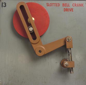
13. Slotted bell crank drive. Circular motion of pin in disk, which works inside of the straight, slotted yoke, produces an irregular, vertical motion of rod. Downward motion of rod is slow but has a quick return. Examination of action of rotating pin in yoke explains this.
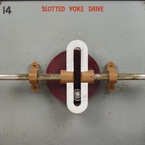
14. Slotted yoke drive. This is an example of rotary motion being converted into straight line motion. So it is opposite to that of No. 12.
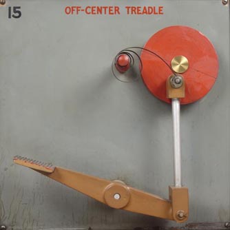
15. Off-center-stop drive. This treadle motion has a spring attachment for bringing the crank A, when action ceases, back to a position off center where it will always start when pressure is applied to the foot lever.
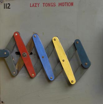
16. Multiple travel movements. Multiple travel movements are very useful. The upper model has a mechanical advantage of 2 to I and the lower model of 8 to I. The latter is that commonly used in expanding gates, doors, etc.
Section II Nos. 17-32, Universal joints, out of line drives, eccentrics, rope and pulley lifts, types of clutches.
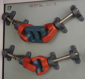
17. Universal joints. A joint is a connecting link between two shafts which are out of line or change position. Its purpose is to transmit power, one end being the driver, the other end being driven, between two shafts which are at any desired angle. A good example of its use is in the automobile where the driven shaft is out of line with the engine or driving power.
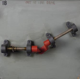
18. Out of line drives. The power is transmitted by joints. No. 18 is a universal joint but of unusual construction, not as practical as those in No. 17.
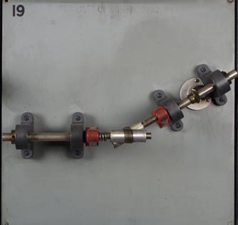
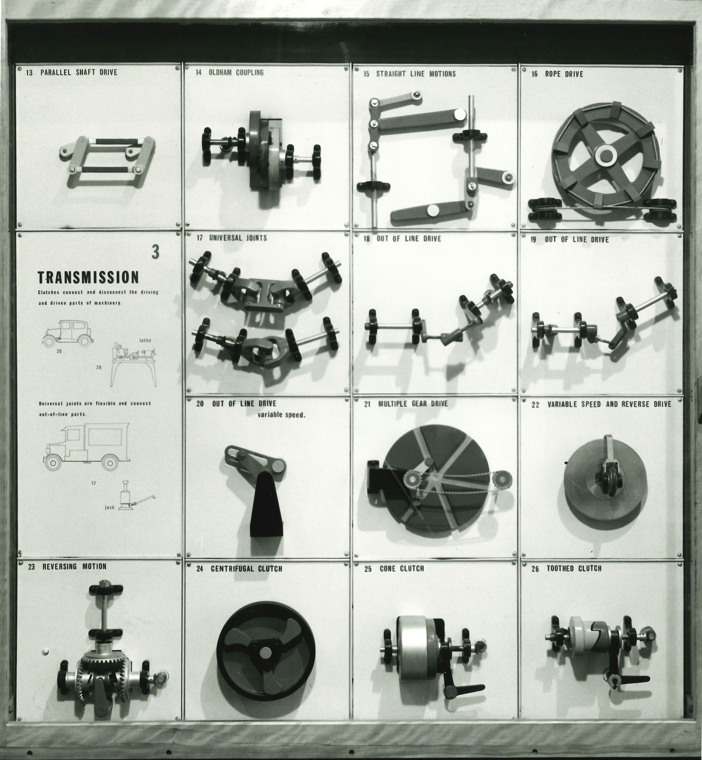
19. Out of line drives. The power in these two out of line drives is transmitted by joints. The joint in No. 19 will only operate when the shafts are placed at the same angle as the angles in the floating tube A, operating between the two driving arms. The placing of the shafts and construction of the tube require great precision.
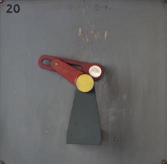
20. Out of line drive. The advantage of this drive is to give a variable speed to the driven shaft to which a rod or other mechanism may be attached. The red slotted arm is the driver and the green crank is driven.
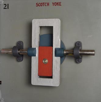
21. Scotch yoke. The green disk carries the driving pin to which is attached a guide, the red block. This guide, working inside of a rectangular yoke, gives a varying speed to the sliding rod, which is slower at the ends than at the center of stroke.
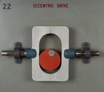
22. Eccentric drive. An eccentric is a revolving disk having the point, on which it revolves, off the center of the disk. The eccentric is the driving force and works in an elongated yoke. This does away with the oscillating motion caused by disks which work in circular guides as in No. 23.
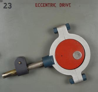
23. Eccentric drive. This type of eccentric is the most commonly used. Application of it can be found in No. 155.
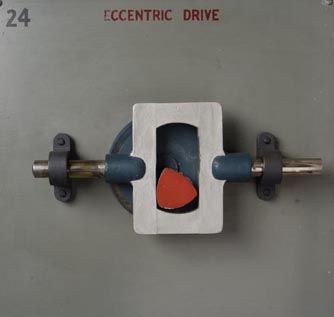
24. Eccentric drive. Attached to the revolving disk in this drive is a triangular cam, which is a projection on a rotating wheel for giving or receiving motion against its edge. In this case, the disk and cam give the motion. The rod is at rest at the completion of each stroke. This form of eccentric is used on a steam-engine in the Paris Mint.
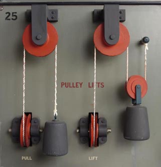
25. Pulley lifts. Pulleys were described in No. 9. The model on the left is a simple fixed pulley for lifting weights. In this, the power
must be equal to the weight to obtain a balance so a one pound pull is needed to lift a weight of one pound.
The second model has two pulleys, the upper fixed, the lower movable. Since there are two ropes, each exerting an upward pull equal to half
the weight, the lifting power is doubled. Therefore a one pound pull will lift a two pound weight.
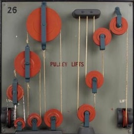
26. Pulley lifts. In this arrangement of pulleys, the mechanical advantage is very high. Note that each cord is attached at one end to a fixed point and to the center of the movable pulley on the other end. The lifting power in the six pulley model (5 movable, 1 fixed) is 26 to 1, and in the four pulley model (8 movable, 1 fixed) it is 8 to 1.
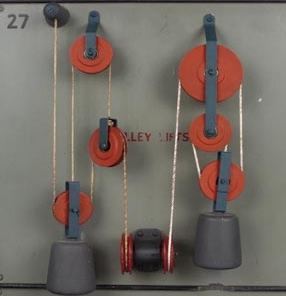
27. Pulley lifts. The first model on this panel combines two movable and one fixed pulley. It has a lifting power of 4 to 1 and is generally
known as a Spanish barton.
The second arrangement has two fixed and one movable pulley. Its lifting power is 8 to I.
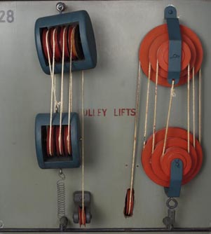
28. Pulley lifts. Two types of "block and tackle." The first has a lower pulley block with three grooved wheels or sheaves and the upper
pulley block has four sheaves. Its lifting ratio is 7 to 1, therefore it will lift seven pounds when one pound pull is exerted on hand rope.
Used most generally in construction work.
The second contrivance is known as White's pulleys, and has a ratio of 6 to I.
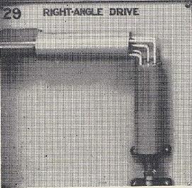
29. Right-angle drive. Between the two revolving drive shafts placed at right angles to one another, are five metal bars bent at right angles. The ends of each are placed in holes in the revolving shafts and are free to be drawn in and out as the shafts rotate. The center is stationary and acts as a guide because it is centered in each shaft. The vertical shaft is the driver in this model. Such a mechanism was used before miter gears were invented.
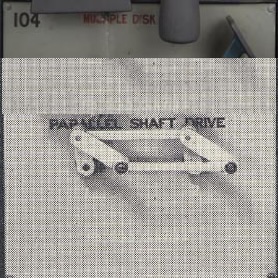
30. Parallel shaft drive. This model represents method of driving parallel shafts 1 and 2, without gears and in the same direction. The front and back cranks or arms connected to shafts 1 and 2 are pinned together at a fixed angle. This device has no dead center because while connecting rod A is in line with shafts I and 2 (or on dead center) B is in driving position (or off center).
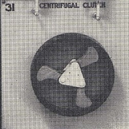
31. Centrifugal clutch. The shaft carrying the red arms is the driver. When driver is at rest, arms are held back by the springs. When shaft is rotating, the weighted arms expand by centrifugal (from the center outward) force overcoming the pull of springs and engaging the drum so that it is made to move.
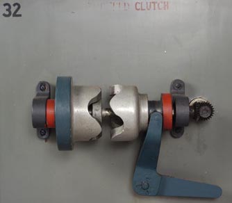
32. Toothed clutch. A clutch is a mechanical device used to connect a driving and a driven member on the same axis. It is operated by the lever and is designed so that the two members may be engaged or disengaged at will. This type is positive and is used where it is not objectionable to start the driven member suddenly, such as in mowing machines. Automobiles employ the other type called the friction clutch.
Section III Nos. 33-48, Countershafts, straight line motions, variable speed devices, cam and miscellaneous motions.
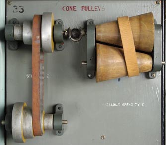
33. Cone pulleys. Step type. The top pulley is the driver. The rate of speed depends upon the diameter of the pulleys. The lower shaft
revolves the slower because the belt is on the small pulley of driver and large pulley of the lower or driven shaft. The speed is reversed
when belt is on large pulley at top and small pulley below.
Variable speed type. The upper cone pulley is the driver and has a constant speed. The position of the belt regulates the speed of the lower
cone, making it variable. When the belt is on the left, the speed is minimum and, as it travels along the cone to the right, it increases
proportionally as the diameter of the lower cone.
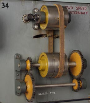
34. Two speed counter shaft. This model is so constructed that two speeds may be transmitted by means of belts, the speed being directly proportional to the diameter of the driving pulley. The upper shaft, with a constant speed, is the driver and has two tight pulleys of varying diameters, A being twice that of B. On the lower or countershaft are four pulleys, the two outer ones are loose and the two inner ones are fixed to the shaft. When the belt on the left is on the loose pulley and is idle, the one on the right is in driving position; therefore a slow motion is transmitted to the lower shaft because the speed obtained is that of the smaller driving pulley above. By shifting the belts, the speed is doubled, because it takes that of the larger driving pulley.
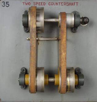
35. Two speed countershaft. No. 35 achieves the same result as No. 34 though the construction is different. The upper shaft is again the driver with a constant speed. On the countershaft are three pulleys, A, B, and C. A and C are fixed, B is loose. Pulley A is connected with the small gear on the left and pulley C with the large gear on the right. When the belt is on pulley B, there is no motion transmitted because the pulley is loose from shaft. When on C, the large gear rotates and the smaller one below meshes with it. Since the small gear has only one fourth as many grooves as the larger, it must go four times as fast to make a complete revolution with the larger gear. Therefore the speed transmitted to the bottom shaft is maximum. When the belt is on pulley A, the small gear on left rotates, causing the large gear below to mesh with it. Now the speed is reversed because of the relation of these two gears. Gears used are the spur type with grooves parallel to shaft. The use for this arrangement is the same as that in No. 34 where power is transmitted by belts and change in speed is needed.
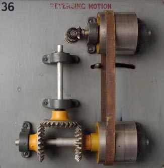
36. Reversing motion. Pulleys A, B and C are arranged like those in No. 35, center loose, and two others fixed. Belt is driven by upper shaft and when it drives pulley A, the vertical shaft travels clockwise. Watch meshing of gears. When belt is on pulley B, there is no transmitted motion, and action of belt on pulley C produces a counter clockwise rotation of the vertical shaft. Left hand gear is connected with pulley C, and right hand gear with pulley A. All three gears are miter gears, having grooves at a 45° angle to the shaft.
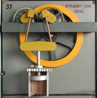
37. Straight line drive. Large fly wheel is on driving shaft, small gear at its center meshes with large gear above which in turn meshes with another gear of equal size. The motion of the two connecting rods attached to these by means of crank arms, brings about a straight line drive on the piston rod. This motion is very powerful, due to the transformation of high speed to low speed. This mechanism is used where great pressure is needed and in high power pumps. It was patented by Dr. Cartwright in 1787 and was used mostly on steam engine piston rods.
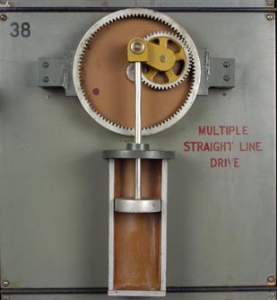
38. Multiple straight line drive. This straight line drive is not as forceful as that of No. 37. The small gear driven by crank pin in red disk, meshes with the large internal gear, thus increasing the speed. An added advantage of this motion is the great multiplication of the distance traveled by piston rod.
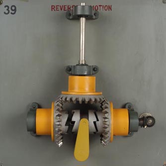
39. Reversing motion. By the use of a toothed clutch, motion is reversed as in No. 36. The lower shaft is driving, and as the clutch member guided by the red arm engages with gear A, the vertical shaft goes clockwise. As gear B is engaged, the motion of vertical shaft is reversed.
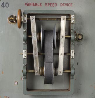
40. Variable speed device. This device is used extensively in variable speed machines where change of speed is desired by simply adjusting red wheel by hand. This turns the right and left hand screw, which adjusts the distance between the upper set of conical flanges. The leather belt is faced with wooden strips, having edges cut to fit the angle of the conical flanges. The upper shaft is the driver and when the flanges riding on this are close together, the belt is forced to a larger diameter on the upper set, but to a correspondingly smaller diameter on the lower set. This transmits a higher speed to the lower shaft. To slacken speed, it is only necessary to turn hand wheel and change position of upper flanges.
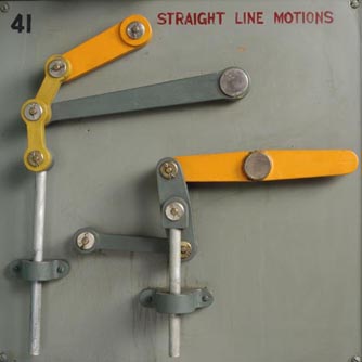
41. Straight line motions. With slight variation in construction, two oscillating horizontal arms, if pinned in a straight line with the vertical rod, produce a straight line motion of this rod. This linkage maintains straight line movement where desired.
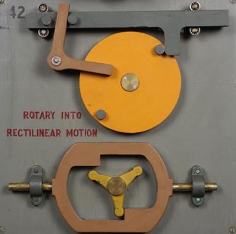
42. Rotary into rectilinear motion. In both these models, a rotary motion is transmitted into a rectilinear motion. In the upper model, the
two studs on the rotating disk strike the elbow shaped arm or bell crank (See No. 10) in rotation and it in turn works between the two studs
on the horizontal bar, pushing it back and forth across a field.
The rectilinear motion of the lower model is caused by the three projections revolving inside of the horizontal shaft. The motion in both
also alternates back and forth.
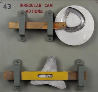
43. Irregular cam motion. The definition of a cam is given on page 67. The shape of the cam on this revolving disk determines the motion of
the rod on bar. Various shapes may be used, depending upon the special motion required.
The cam in the lower model simply suggests another motion.
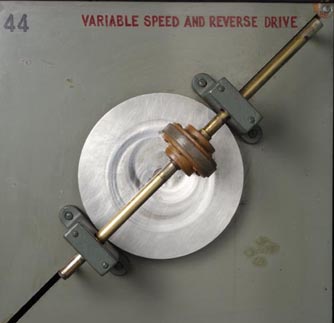
44. Variable speed and reverse drive. The revolving disk is the driver, transmitting power to shaft carrying vertical wheel. This form of drive does two things-it varies the speed and reverses the motion of the driven shaft. The vertical wheel increases in speed as it is moved away from the center and reverses as it crosses center of driving disk. Such a device has been used on automobiles and does away with shifting gears, but it has not been found practical because of the high friction.
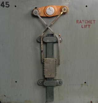
45. Ratchet lift. As the red lever oscillates, it operates two hooked pawls on the ratchet bar A and lifts the bar. The slot serves as a guide. Used in various ways where it is desirable to hold work at different levels of operation and in fixed position because ratchet only operates in one direction.
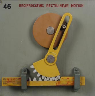
46. Reciprocating rectilinear motion. This combination gives a slow advance and quick return motion to reciprocating bar A. The pin in revolving disk as it changes position working inside the slotted arm causes this reciprocating motion.
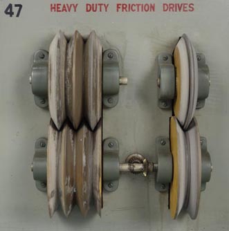
47. Heavy duty friction drives. These drives have a large friction area so that a good grip is made between the two members. These types are used wherever friction drives are necessary.
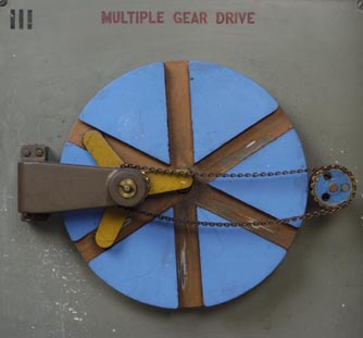
48. Multiple gear drive. This model illustrates a method for reducing speed and obtaining an out of line or off center drive. The shaft carrying the three red arms revolves twice for one revolution of the green slotted disk.
Section IV Nos. 49-64, Ratchet wheels, drives, stops and miscellaneous movements used in machine construction, types of power saws.
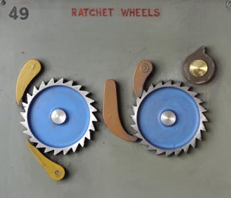
49. Ratchets, pawls and stops. Ratchet mechanisms occur in a great variety of forms. A ratchet consists of a wheel with teeth called the
ratchet wheel which receives periodic or intermittent motion from a swinging member called a ratch or pawl. Another pawl prevents backward
motion, this is called a stop pawl.
Model 1 shows three kinds of stop pawls, each form being necessary to perform its function under different conditions of space in mechanisms
to which they are attached. A is the hook type and prevents backward motion by engaging with teeth. B is the straight type and acts as a
barrier. Both of these have spring tensions to keep them in place. C is the gravity type, which is held in place by its weight below center.
In Model 2, motion is transmitted to the ratchet wheel by the revolving pawl drive. The stop pawl is of the straight type.
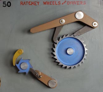
50. Pawl drives and stops. The top model has an almost continuous motion. Watch action of stop pawl. The driver, having both pawls attached
to it, acts as both stop and driver alternately.
In the bottom model, the stop and driving pawls are independent. This is used in many ways, particularly in connection with counting devices
on automatic machines.
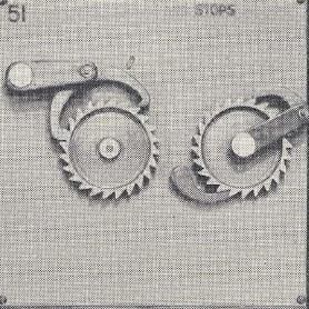
51. Pawl drives and stops. These two types of ratchet movements are used where slow rotations are necessary, such as on feeding mechanisms in textile machinery.
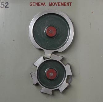
52. Geneva movement. Geneva movement is so called because of its use in Geneva watches as a stop wind. The projection on the driving disk acts as the pawl drive, and the concave projections on the lower disc act as stop pawls. This is used at the present time in motion picture machines for moving the film in front of the lens and is known as the intermittent movement. If applied as a stop wind, one of the concave projections must be shaped convex, and the rotation is stopped.
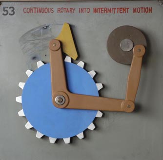
53. Continuous rotary into intermittent motion. Attached to a revolving disk by means of the green arm, is an elbow shaped lever or bell crank (See No. 10). The pawl, attached to this, drives the notched wheel. The desired direction is attained by placing part marked Reverse on right or left of center.
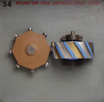
54. Intermittent from continuous rotary motion. The green wheel on horizontal shaft is driving the vertical shaft at right angles through the medium of the toothed drum. The motion of the driver is continuous but that of the drum is intermittent because there is a slight pause between the time a projection on the driver leaves one groove on the drum and enters the next.
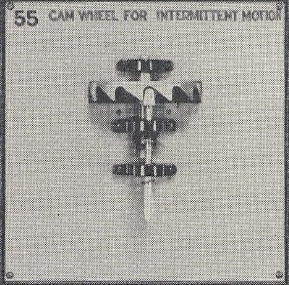
55. Cam wheel for intermittent motion. The cam as previously explained is a projection on a rotating wheel for giving or receiving motion against its edge (See No. 24). The shape and size of this edge determines the resultant motion of the follower, which is the rod working through guides. This model is so constructed that the constant rotary motion of the cam wheel is converted into intermittent vertical motion.
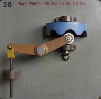
56. Wave wheel for oscillating motion. There is great similarity between this model and No. 55. No. 56 shows three types of motion; continuous rotary as in the wave wheel, oscillating or swinging as in the lever, and intermittent as in the rod.
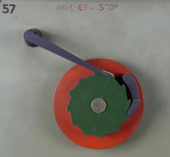
57. Jump motion device. The main parts of this device are the worm wheel (above) and worm gear (below). The motion of the worm wheel is continuous because it is on the driving shaft. The teeth on the vertical worm gear mesh with the horizontal worm wheel. When the gear has revolved sufficiently to escape contact on the worm wheel, the red weight (by gravity) advances the gear very quickly to meet the worm and repeat the process. In one cycle, the motion is controlled to be slow when meshing with gear, and very fast when jumping.
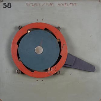
58. Ratchet and pawl movement. This is a step ratchet for heavy duty and is very commonly used for pipe cutting dies, ratchet wrenches, etc.
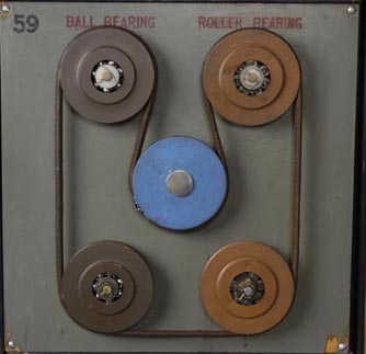
59. Ball bearings. Roller bearings. Bearings are the supports for rotating members or shafts and the term as generally applied includes the whole support. The friction caused by the moving body in the bearing has always been a great problem, until the introduction of ball and roller bearings which are called anti-friction bearings.
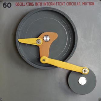
60. Oscillating into intermittent circular motion. The kind of motion and its direction in this model are dependent upon the position of the two green arms, A and B. The rotation of the crank arm which is attached to the driving shaft gives an oscillating motion to the connecting rod, at the other end of which is another crank arm pinned to the center of the rotating disk. If A engages the drum, the resulting motion is intermittent and clockwise; if B engages the drum, the direction is reversed; and if both A and B touch the drum it oscillates in one position.
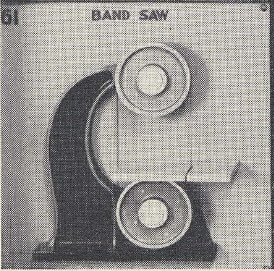
61. Band saw. The constant rotary motion of the driving pulley (lower) produces a continuous straight line motion of the straight parts of the saw. The upper pulley is a guide. This type is used at high speed for cutting wood or other substances. When run at low speed with high-tempered steel it is used on metals.
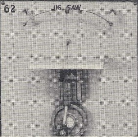
62. Jig saw. The vertical saw is drawn down by crank pin, cutting material and is then drawn back by tension of spring above. This type is used for sawing irregular shapes in wood and later the band saw was developed from it. It is possible to saw inside of a form by placing the saw blade through a hole in the work before fastening to spring. When job is complete, saw is loosened and work slipped off.
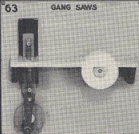
63. Gang saws, vertical and circular types. The word gang is used when more than one saw is combined to operate at the same time. In the vertical type the power is supplied by a pin on the rotating red disk. A connecting rod is used to transmit the power. This type is used to cut on down stroke only.
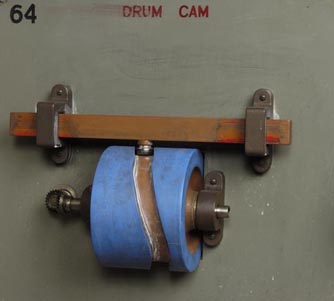
64. Drum cam. This shows another way in which a cam may be used. The intermittent motion given to the traveling arm depends on the angle or shape of groove in drum. This motion can be worked into many combinations and is used in numberless ways, particularly on automatic screw-cutting machines.
Section V Nos. 65-80, Gearing group, all types of gearing used in machine construction, gear combinations.
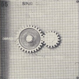
65. Spur gears. Gears are used to transmit power from one shaft to another and are now used in practically every complicated machine. There are a variety of types. This model shows ordinary spur gears, having grooves parallel to the shaft. When the large gear is the driver the small one is driven at a greater speed having eighteen teeth to the thirty of the driving gear. When the small gear is the driver, the large one revolves at a correspondingly slower speed.
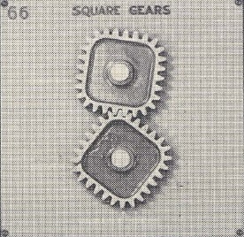
66. Square gears. This type of gearing transmits a variable speed. The top gear is the driver and has a constant speed. The lower gear runs slow when the corners are up in position and faster when driver engages the flat sides. This type is not commonly used.
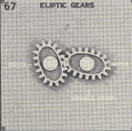
67. Elliptic gears. These are the most common of the non-circular gears. Left gear running constant, drives right gear at a variable speed depending upon the shape of the ellipse. Used in certain types of printing presses.
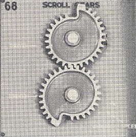
68. Scroll gears. This type of gearing produces a gradual increasing and decreasing speed during one revolution. The speed of driven gear is slowest when its longest point from center is engaged with driver. There are a variety of scroll gears to suit the condition of motion required.
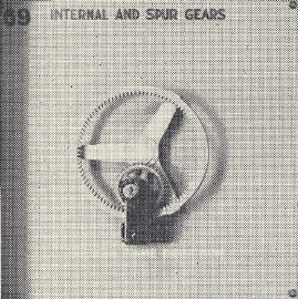
69. Internal and spur gears. This shows two types of gears, internal and external spur gears in combination. Note that the large internal gear is driving a small spur gear and both are turning in the same direction. Referring to No. 65, you will see that spur gears in combination turn in opposite directions. Application of this combination may be found in No. 38.
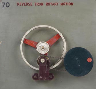
70. Reverse from rotary motion. There are three gears in combination in this model-internal, spur, and mutilated gear in center. The large or internal gear and mutilated gear are both drivers. When the teeth on the internal gear mesh with the teeth on the small spur gear the motion is in one direction. When teeth in the mutilated gear mesh with spur gear the action is reversed. The red target disk indicates this. Motion is transmitted to the target disk by a chain drive (See No. 7.) This movement is usable in any type of machine where advance is slow and return fast or vice versa.
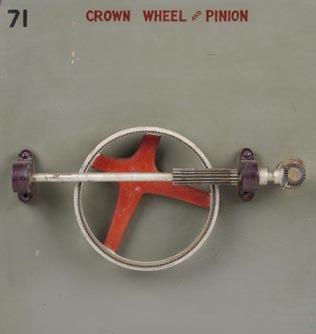
71. Crown wheel and pinion. The cogwheel or pinion rotating on the horizontal shaft is driving the large crown wheel. The pinion runs at constant speed because it is on the driving shaft but that of the crown wheel varies at every point from slower to faster movement because it rotates on a point off-center.
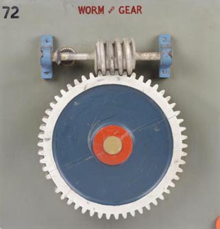
72. Worm and gear. The worm or continuous screw on the horizontal shaft is the driver. This combination reduces the speed of the driven member and also multiplies its power. The power increases proportionally as the speed decreases. The speed ratio of shafts depends upon the relation of number of threads on the worm (single or multiple) to the number of teeth in the worm wheel or gear. This type of speed reducer is used between shafts at right angles to each other.
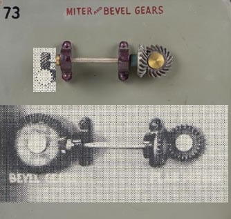
73. Miter and bevel gears. The miter gears are the two models on the right. Miter gears are used to transmit motion between two shafts placed at right angles to each other. Since the gears are of equal diameter, they both revolve at the same speed. The angle of the grooves to the shaft is 45° in all miter gears. Helical miters are so cut that they are noiseless. Therefore they are used for high speed transmission.
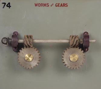
74. Worms and gears. This combination shows the method of changing rotation of driven gear. Note the right and left hand angle of the threads in the continuous screw or worm. Teeth in lower gears have corresponding left and right angles. The threads of these worms are of the multiple type and have five leads while that in No. 72 is a single thread, having only one lead.
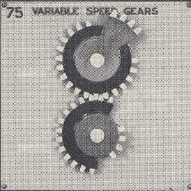
75. Variable speed gears. In this combination of gears there are two speeds and a stop movement due to the relation of the diameters of the parts that mesh. When the teeth of equal diameters are meshed, as on black sectors, both gears turn at the same speed. But when red sectors are in mesh the speed of the lower gear is doubled because it has a diameter of four inches while that of the upper projection is eight inches. When no gears mesh, there is a stop in the rotation of the lower gear.
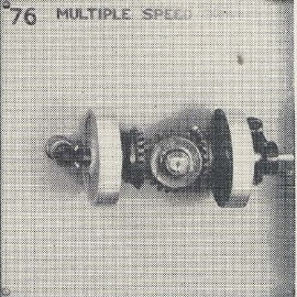
76. Multiple speed drive. When more than two gears are in mesh such a combination is a train of mechanisms and is called a gear train or a train of gears. This train of gears is of a special type called epicyclic, because the one on the left is fixed and the horizontal gear is carried on a shaft which rotates about the axis of the fixed gear. The gear on the right is attached to the driven shaft and is made to rotate at double speed, being the sum of two movements of the horizontal gear, its rotation on its own axis and its meshing with the fixed gear about which it rotates.
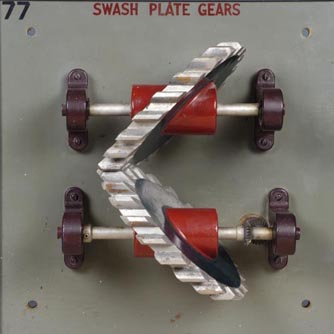
77. Swash plate gears. This combination of gears is unusual and the only known application was in a dough-mixing machine. The action is identical with two plain spur gears of same diameter. Close observation will show that the teeth are cut parallel with the shafts and all are the same distance from their respective centers. Take a diagonal slice from a great length of a spur gear, and the result is a swash plate gear.
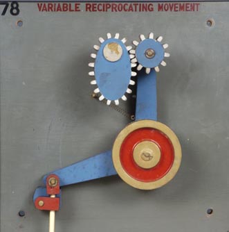
78. Variable reciprocating movement. The combination of gearing in this model produces a variable speed and movement of the lever and arm. Many different combinations are worked out in this manner. A particular use is in textile machinery.
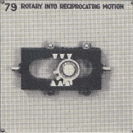
79. Rotary into reciprocating motion. The constant rotation of the four-toothed wheel inside of a specially constructed rack gives the reciprocating motion to the shaft through alternate meshing of the teeth on rack.
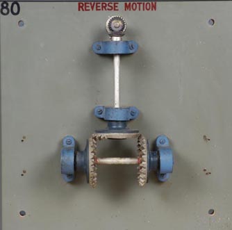
80. Reverse motion. The reverse motion of the driven shaft is caused by the meshing of a mutilated bevel gear with two bevel gears at right angles to it. It is also caused because the meshing of the gears is on opposite sides of the driver. The motion of both the driving and driven shafts is rotary. Compare action to that in No. 39.
Section VI Nos. 81-96, Household devices, coal breaker rolls, stone crusher, four early types of power devices.
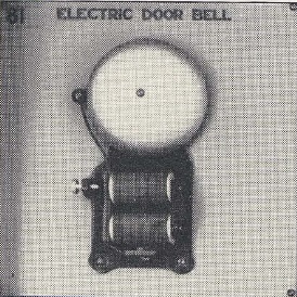
81. Electric door bell. When the button is pushed, the current flows through the green coils. This produces a magnetic pull which attracts the red iron bar, causing the clapper to strike the bell. As the red bar swings, it pulls the spring away from the screw contact and breaks the circuit. This stops the current so that there is no longer a magnetic pull and the bar is released. In springing back, the circuit is closed again and the process is repeated to produce a continuous ringing bell.
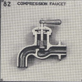
82. Compression faucet. The faucets in our houses are merely valves for opening and closing pipes. The compression faucet is the common type. The handle operates a screw which forces a disk faced with a fiber washer against a circular opening, and so shuts off the water. If the handle is turned the other way, the disk is raised, leaving an opening so that the water flows. When the washer wears out, the connection is faulty, causing a leakage.
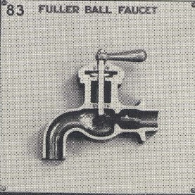
83. Fuller ball faucet. In this model, a crank is used to open the valve instead of a screw. When crank is turned, stop washer A is forced back against water pressure and water rushes through the spigot. When crank is released, pressure of water in pipe closes stop A.
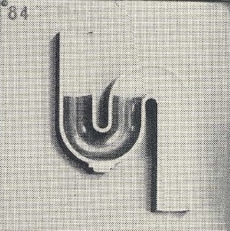
84. "S" trap or water seal. Correct drainage in a house is very essential. A trap is a fixture placed in a waste pipe below the plumbing fixture to prevent gases from entering the house from the soil pipe or sewer. Advantage is taken of the fact that a gas will not force its way into water to a lower point. The water is represented by the green color. This type of trap is universally used.
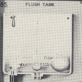
85. Flush tank. As the handle is operated, the stop washer connected to it by a long rod is raised, opening a valve and forcing the water to leave the tank. See valve connections in faucets Nos. 82 and 83. The float ball descends with the water, thus opening the inlet valve to get a fresh supply of water. As water enters inlet valve, float rises, closing it to prevent overflow.
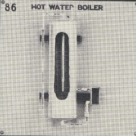
86. Hot water boiler. The little red arrows will show you the course of the water through the boiler. It enters cold water inlet on left from street mains and flows through a pipe which reaches nearly to the bottom of the tank. From here it is led off to the heater where it flows through coils, is heated and returns to the tank nearer the top, leaving at hot water outlet. This causes a circulation which continues until all the water in the tank has passed through the heater and the whole tankful is hot.
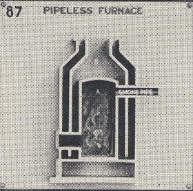
87. Pipeless furnace. Pipeless furnace is a device for circulating warm air through a house. Air is warmed by coming in contact with heated walls around fire box A, and rises through passages B. As warm air rises through the center of registers the cold air is automatically drawn downward through outer ring of registers into cold air duct C where it is warmed and returned, causing continual circulation of warm air through the house. An inlet pipe from out-of-doors may be used and regulated for desired fresh air.
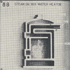
88. Steam or hot water heater. Heat generated in fire box A, heats walls of furnace and surfaces going to smoke pipe, raising water in red sections to steam heat. Steam rising in steam dome is transmitted to steam pipes and radiators in building for heat desired.
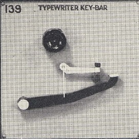
89. Typewriter key bar. When key bar is struck by operator, the type bar is raised quickly by the connecting rod, striking the platen or roller and making the impression upon the paper through the typewriter ribbon which is held in front of platen. Recovery to original position is made by action of a tension spring.
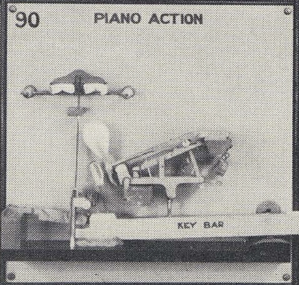
90. Piano action. When ivory end of key bar is pressed down, hammer A is caused to strike a quick blow on piano string, rebounding to allow string to vibrate. A quick rebound is caused by the elasticity of both the compressed felt in the hammer-head and the steel piano string. Under normal conditions of playing, the damper immediately touches string, causing vibrations to cease, thereby stopping tone. When full volume of piano is needed, the loud pedal is pressed with the foot to cease operation of damper, allowing string to vibrate fully, giving large and sustained tones. The intricate mechanism is necessary to cause a quick return of hammer for rapid playing and to prevent resonance when repeating action is desired.
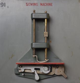
91. Sewing machine. This is the lock stitch type machine. To show complete operation, material for sewing must operate through machine. As needle goes through material, foot bar presses foot down. When needle rises and draws thread up through material the foot rises and the toothed feeder under foot advances material the required distance for next stitch. On first operation, when needle goes downward through material, the loop of thread is caught by revolving thread hook, which pulls thread taut in material. The repeating of this cycle, produces a series of stitches continuously along a desired line. Desired length of stitch is regulated by feed adjustment.
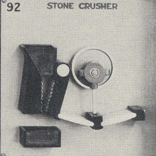
92. Stone crusher. This mechanism requires a very heavy pressure. Therefore a toggle joint is employed which is attached to the hinged jaw and is driven by an eccentric (See No. 23). In a toggle joint, two bars are joined together end to end but not in line, so that when a force is applied which tends to straighten out the arrangement, a great pressure is exerted, in this case, to the hinged jaws. A large stone or boulder is placed in the hopper and, as it moves by its own weight to the lower end of the jaws, it is crushed smaller and smaller till it falls through.
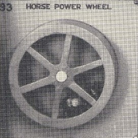
93. Horse power wheel. The weight of the horse attempting to climb the side of the wheel causes the wheel to rotate. To the shaft of this wheel a belted pulley may be attached for transmission of power. This is a very early source of power but is still in use in isolated parts of the world.
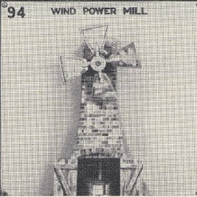
94. Wind power mill. The velocity of the wind drives the wheel, which has blades that can be set at various angles in order to obtain a desired speed. The revolving shaft having one grinder attached to it works against the other. This early type was used for grinding grain.
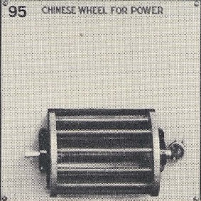
95. Chinese wheel for power. This wheel was first known as the "Chinese" wheel and was used to punish criminals and slaves. They were forced to tread the rungs in the wheel and so work out their punishment in labor. Then the wheel was equipped with a belt and pulley for transmitting power.
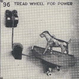
96. Tread wheel for power. The power in this device is obtained by the action of animals traveling on the inclined plane. It was generally used in the early days in rural districts for churning and light work. Animals most generally adapted to this were dogs, goats, and sheep.
Section VII Nos. 97-112, Automobile section, showing different parts in detail, Hydraulic jack and miscellaneous devices.
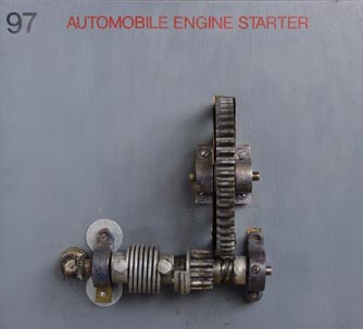
97. Automobile engine starter. This device known as the "Bendix drive" is the starter. The starting motor is attached to the left end of shaft. As the starting pedal is pushed, the motor starts the shaft at a high speed, sending the small gear in mesh with the teeth on the fly wheel. The spring absorbs the starting shock. This starts the engine (See No. 102), which soon picks up speed so that the fly wheel revolves faster than the small gear. This action causes the small gear, still meshed with it, to rotate on the threads of the starting shaft, now slowing down, and throws it back to its first position and out of mesh with the fly wheel.
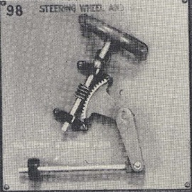
98. Steering wheel and gear. The steering mechanism in this model is known as the worm and gear type. The action of the worm and gear is very strong. Use is made of a bell crank drive (See No. 10). The horizontal rod is connected to the steering arm on the front wheels.
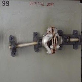
99. Universal joint. There are many forms of universal joints (See Section II). The advantage of this form is that it is noiseless in its action. The leather disks are very flexible and keep changing position. It is necessary to use a universal joint as the engine shaft and drive shaft are always out of line and every vibration of car changes angle.
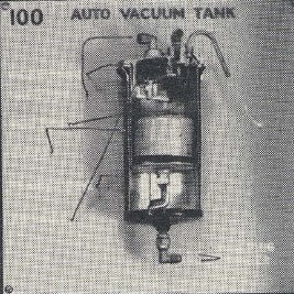
100. Auto vacuum tank. This shows a standard type of vacuum tank used to keep the carburetor supplied with liquid fuel all the time the engine is running, from the supply tank which is at a lower level than the carburetor. When a vacuum is caused in the tank by the piston action of engine (See No. 102), through supply tank, gasoline is sucked up from the supply tank, entering through vacuum valve. As the tank is filled, the float rises, causing the lever arms attached above it to operate. This closes vacuum valve and opens air valve in vent tube, allowing air to enter from outside. As the engine runs, the gasoline within the lower part of the vacuum tank is supplied to the carburetor, and as it does so, the float falls with the gasoline level. When the level falls sufficiently, the little springs and the float operate the valves again and the operation is automatically repeated.
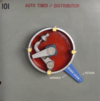
101. Auto timer and distributor. In an internal combustion engine, it is very necessary that the igniting spark occur only in the cylinder that is ready to be fired and at the right time in the cycle of operations. The timer and distributor is the device which regulates this action. The revolving arm is rotated by cam shaft of the engine (See No. 102). As it revolves, it closes contact with the four terminals on the shell of timer, causing current to go to spark plugs on the engine and fire them in regular order. In this model the firing order is 1, 3, 4, 2. The other arm, called the breaker arm breaks the current at each contact point as revolving arm travels against cam attached to it.
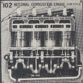
102. Internal combustion engine, four cycle. This is called a four cycle, four cylinder motor because of the four steps in the process,
repeating themselves in each one of the four cylinders. It is also called a combustion engine because the power is obtained by the rapid
burning or combustion of a liquid, forming a gas which expands and exerts great pressure. The four steps in the process are the loading,
compressing, firing, and exhausting or clearing. As the action is the same in all cylinders, the one on the right will serve as a good
example.
Step 1. As the engine is started by the starting device (See No. 97), the piston head starts downward and sucks a charge of vaporized
gasoline in through the inlet valve from the carburetor (See No. 100 and No. 110). The piston is attached to the lower shaft, called the
crank shaft, by the connecting rod. Connected to the crank shaft by means of gears is the cam shaft. The upper gear is four times larger
than the lower, therefore the upper or cam shaft rotates only once while the lower rotates four times. This regulates the next step.
Step 2. As the piston starts back, the inlet and exhaust valves are both closed by the action of the cam on the cam shaft, and the gas is
compressed above the piston head.
Step 3. At the end of the up stroke, the timer delivers current to the spark plug, making a spark which fires or explodes the compressed gas
at the proper time causing the piston to go down. This is called the power stroke for it transmits a rotary motion through the crank shaft
to the drive shaft of the car.
Step 4. At the end of the power stroke, the exhaust valve is opened and the piston returning upward forces the used gas out through the
valve into the muffler and into the air. Beginning at the right, the order of firing of the cylinders is 1, 3, 4, 2. The continuous
explosion of gas causes the engine to heat up. Therefore a cooling system is needed, as shown in No. 103.
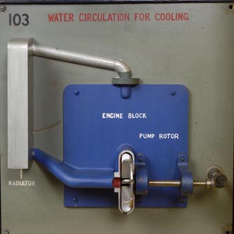
103. Water circulation for cooling. The circulating pump system shown in this model is most generally used today. As the water is heated it rises to the top of the water jacket and travels through this pipe into the top of the radiator. A cooling fan draws cold air in through the openings of the radiator and cools the water. The cool water is then drawn down through the radiator by gravity and by the pump rotor and enters the lower part of the water jacket to repeat its cooling action.
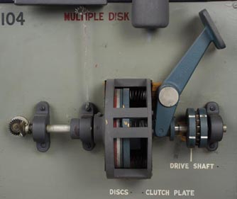
104. Multiple disk clutch. Clutches were explained in No. 32. This type is a friction clutch. The shaft on the left is connected to the crank shaft of the engine (See No. 102). The two driving disks are mounted one on the crank shaft end, being the clutch plate, and one on the drive shaft end. The clutch plate is fixed on a sleeve and slides on the crank shaft. The red and white disk on the right connects with the transmission (see No. 108). In front of the clutch plate are several disks mounted loosely on the crank shaft. When clutch pedal is pressed down, clutch plate and loosely mounted disks are parted, thereby breaking connection with the engine. When the clutch pedal is left in place the clutch plate gradually engages with the multiple disks, thereby starting the car. Multiple disks afford a smooth starting and less wear, because the friction is distributed in all disks.
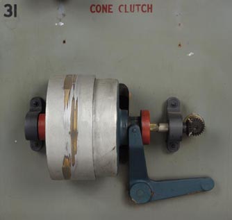
105. Cone clutch. This is one of the earliest types of clutch used in automobiles. It is no longer used because the shock at starting was too great and the wear excessive.
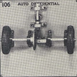
106. Auto differential. The differential in this model is the set of four miter gears in a bracket, connected with the shafts of the rear wheels. The purpose of this device is to allow one wheel to rotate with a different speed than the other if necessary, for example, in turning a corner. The small miter gears of the differential do not revolve when both wheels are running at the same speed but simply act as a lock between the driving sections of the two wheels. When there is a difference in speed, the two horizontal gears revolve on their own pinions and compensate for the difference. At the same time they keep the driving contact between the two sections of the axle.
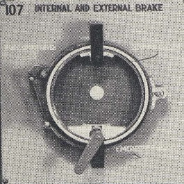
107. Internal and external brake. The working of foot and emergency brakes is shown in this model. When the foot brake lever is pressed down it operates the lever on the left and by toggle action (See No. 92), tightens the brake bands on outside of brake drum, retarding it according to the pressure exerted on the foot pedal. When the emergency lever is operated the same action on bottom of lever turns the eccentric cam, with powerful action, expanding the brake band on the inside of the drum with the same result.
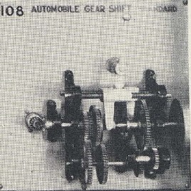
108. Automobile gear shift, standard. The upper revolving shaft is connected on the left end to the engine through the clutch. The right end of shaft is connected to the drive shaft of the car which runs to the rear axle. This shaft is cut in two between the yellow and blue gears, each part revolves separately. The small or intermediate shaft carries reversing gear. The lower revolving or jack shaft carries four gears, all fixed. These mesh with upper gears to give the three speeds forward (low, intermediate, and high) and reverse. On the left, the two yellow gears always mesh. The upper shaft drives the lower, getting its power from the engine, reducing the speed of the lower shaft because the driving gear is smaller than the driven gear. On the right, the two lower red gears always mesh. When in reverse position, all red gears on right are in mesh. Follow motion of yellow gears and red gears to understand reverse action. When in low or first position, the green and red gears on the right mesh. The speed is low because a large gear on the upper shaft meshes with a much smaller one on the lower shaft, the lower gear now being the driver. In second or intermediate position, the two blue gears mesh, the speed of the upper shaft being the same as the lower, both gears being the same diameter. This speed is greater however, than when in low. In third position or high, the yellow gear on the left locks inside of the blue gear. Now the speed transmitted is high because the driven gear is locked with the drive gear which runs at engine speed.
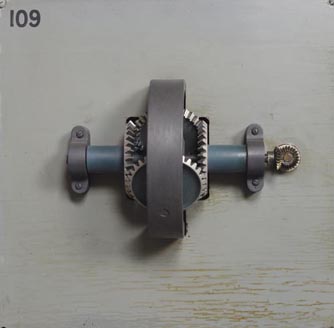
109. Power measuring dynamometer. The purpose of this device is to measure the power required to drive a particular mechanism. It depends principally upon the action of a train of four bevel gears and a hoop-shaped frame. The two horizontal gears and the frame in which they are arranged revolve freely on the middle of the horizontal shaft, on which there are two vertical gears, the one on the right stationary, the other loose on the shaft. The vertical gears mesh with the horizontal gears. If a load is put on the gear loose on shaft at left, the power required to hold the hoop stationary is the power required to carry the load. This is measured by any device made to stop rotation of hoop which is attached to a recording arm which registers on scale.
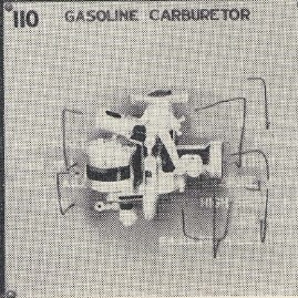
110. Gasoline carburetor. The duty of the carburetor is to mix the fuel and air and insure the proper proportion of each before it is sent
to the cylinder to be burned. Gasoline is supplied to the carburetor from the main supply tank by means of the vacuum tank (See No. 100).
The carburetor converts the fuel into a vapor by mixing it with air.
Gasoline enters float chamber from vacuum tank (See No. 100), through needle valve attached by a lever on the float. When a sufficient
supply is in, the float rises and valve closes. This float automatically keeps gasoline at proper level as in vacuum tank. Gasoline is then
sucked into the mixing chamber in center by the action of engine pistons (See No. 102). It is mixed with air, admitted through air valve,
which vaporizes it as it passes into distributor pipe or manifold for entrance into cylinders (See No. 102). When engine is running at a
very high speed and additional gasoline is needed, it is drawn through the high speed jet. The throttle valve at top regulates the gas flow
to the engine, thereby controlling its speed. The choke is used in starting when the motor is cold and the mixture will not explode
properly. The air inlet is closed so that more gas enters the mixing chamber giving a richer mixture. The heat pipe leads from the exhaust
manifold. Heat is drawn into the heat jacket around the carburetor which aids in vaporizing the gasoline, particularly in cold weather.
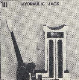
111. Hydraulic jack. A hydraulic jack is very powerful. A small force will exert a tremendous lifting power. Pressure applied to the lever causes the valve A at opening of liquid chamber to open so that liquid is drawn from it and flows toward center cylinder. The lever returning in the opposite direction opens valve B into cylinder below ram allowing the liquid to rise in it and raise the ram. The great lifting power depends on the length of the lever and the size of the plunger attached to it. The longer the lever and smaller the plunger, the greater the force.
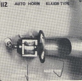
112. Auto horn, Klaxon type. This is the usual type automobile horn. The motor causes the vibrator or cam wheel to revolve against the button mounted on sound disk, causing it to vibrate. The greater the number of vibrations, the higher the pitch or tone. The horn or resonator amplifies the sound.
Section VIII Nos. 113-128, Water handling and water power devices, propeller wheel and steering device.
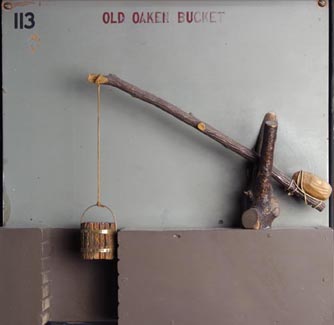
113. Old oaken bucket. This is the first known method of raising water from a well of no considerable depth. Use is made of a lever of the first type (See first model on No. 2). The rock or counter balance attached to the boom assists in lifting the bucket because it equals about one-half of the weight to be raised.
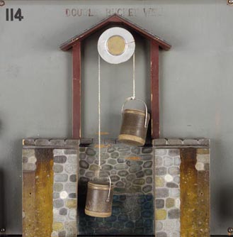
114. Double bucket well. Another method for raising water makes use of the common pulley (See No. 25). The empty bucket is pulled down in order to raise the full one.
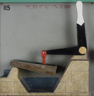
115. Bailing or lifting scoop. This device is for raising water short distances. The scoop is connected by a rod to one end of the green elbow lever which has force applied at its other end.
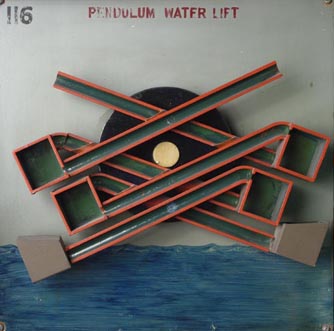
116. Pendulum water lift. This device for raising water is operated by hand or other power. By following the arrows leading from each pick-up bucket to the overflow it is easy to trace the action, the whole device oscillating on the center represented by red disk.
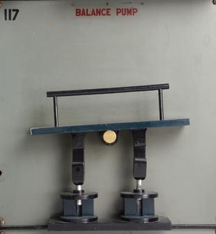
117. Balance pump. This type of pump was an early form, operated by a man swaying from right to left over the center of the bridge. Slaves and criminals were commonly used and so worked out their sentences in labor. The two plungers represent valve pumps.
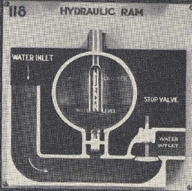
118. Hydraulic ram. This machine for raising water will furnish a supply of water at a high level. The alternate action of the two valves operated by the force of the moving water, allows the water to enter the air chamber. The valve on the right is kept open by its own weight until sufficient water has entered the inlet and forced it shut. As stop valve closes, the small valve is forced open and water enters the air chamber rising to a certain level with pressure that equalizes the air pressure. When the small valve closes again, the right-hand one opens. A constant upward stream into tank is obtained by the compressed air in chamber acting on surface of water.
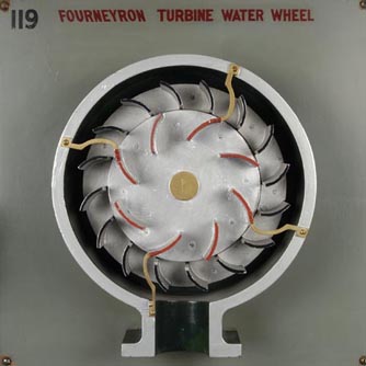
119. Fourneyron turbine water wheel. As the water enters the holes in the center, it flows against the fixed guides or shutes. These direct the water against the buckets of the outer wheel, causing it to revolve. The water then escapes through discharge.
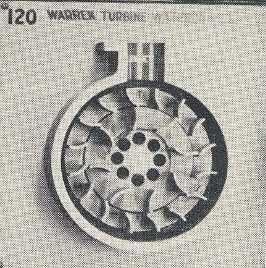
120. Warren turbine water wheel. In this type of turbine water wheel the position of fixed guides and revolving wheel is opposite to that in No. 119. Water enters inlet at top and falling upon fixed guides on outside is directed upon center wheel, causing it to rotate. Water is discharged through holes at the center.
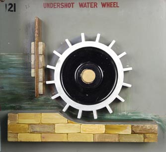
121. Undershot water wheel. The motion is caused by the water flowing under gate on left pushing against the wheel. The speed of the wheel is regulated by raising and lowering the gate valve, allowing more or less water to flow through.
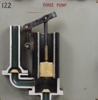
122. Lift and force pump. This is the ordinary force pump having two valves. The plunger is raised by the handle causing valve A to rise, drawing water from low level into the pump chamber. On the descent of plunger, valve A closes and water is forced through valve B into discharge pipe at higher level. As handle is again raised, water in discharge pipe closes valve B.
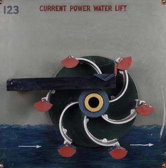
123. Current power water lift. This device is sometimes called a Persian wheel. It has a hollow shaft in the center and curved buckets, at the ends of which other forms of buckets are suspended. The motive power is supplied by the end buckets which turn as water strikes them and present a good driving surface. Their under surfaces offer no resistance because they travel in direction of water. This is one of a few instances where the motive force also carries a load. As the wheel rotates, all buckets pick up water. The small buckets discharge water at the top after being tilted by a stationary pin and the curved buckets discharge water through the hollow shaft in center.
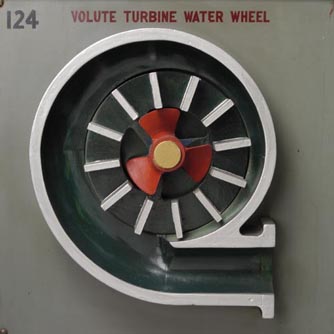
124. Volute turbine water wheel. This type water motor is used for furnishing power. Water, entering at the inlet, flows around inside of gradually narrowing passage between vanes and outer shell, or casing, and causes vanes to rotate. Great pressure is exerted by the water seeking to escape. As the water escapes through the discharge at center, it is forced against the radial surfaces of the red propeller wheel and again exerts power on the drive shaft A.
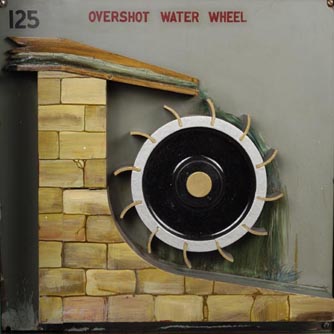
125. Over-shot water wheel. Motion is given to wheel by force of water striking against the buckets at top of wheel, and also by the weight of the water in the buckets as they rotate downward.
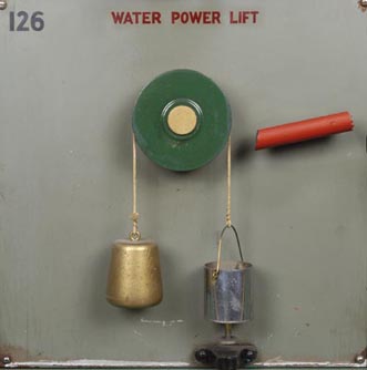
126. Archimedes screw. This machine is said to have been introduced by Archimedes. The motive power is supplied by the stream, rotating the green wheel. As spiral pipe, represented by glass, is rotated by the wheel, water runs in lower end seeking its level on the lower side of turn in pipe. This lower level advances with the spiral shape of pipe and water is automatically raised to the top and discharged. Note travel of water as represented by balls in bottom of each turn of coils.
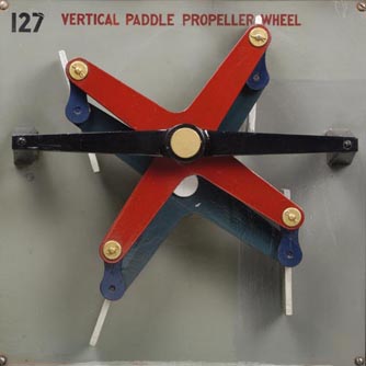
127. Vertical paddle propeller wheel. This is the most efficient type of paddle wheel. The green driver arms are the supports for the rotating paddles. The red arms are attached by crank arms to the green arms. The red driver is eccentric to the green driver. The rotating action of the two causes the paddles through the crank arm connections to be held always in a vertical position with their surfaces always meeting the water at right angles to their travel. This is the most efficient angle for driving.
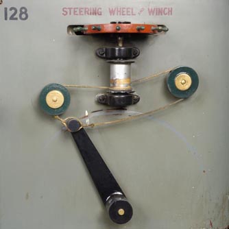
128. Steering wheel and winch. Ordinary steering apparatus. On the shaft of the hand wheel is a barrel on which is wound a rope. The ends of the rope pass around guide pulleys and are attached to a lever or tiller on the top of the rudder. By turning the wheel in opposite directions, the rope will wind and unwind, pulling the lever in the direction the wheel is turned.
Section IX Nos. 129-144, Clock escapements showing the development of clock and watch mechanisms, machine tool mechanisms.
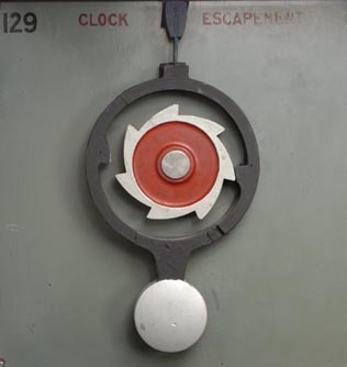
129. Clock escapement. An escapement is a combination in which a toothed wheel acts upon two distinct pieces or pallets attached to a reciprocating frame. The frame is so arranged that when one tooth escapes or ceases to drive its pallet, another tooth shall begin its action on another pallet. The object of an escapement in a clock or watch is to stop and then set in motion again, at regular intervals, every wheel in the entire train of mechanisms. This action causes the familiar tick of a clock and watch. The rotating toothed wheel is the driver and gives a swinging or oscillating motion to the driven member. This type of escapement was used on the first clock movements when whole works were made of wood.
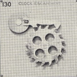
130. Clock escapement. In this model, the arm which holds the pallets is guided by a pin fastened to the red disk. The wheel is kept from escaping or making a continuous rotary movement, by the alternate action of the pallets entering and retiring from between the teeth of the escape wheel.
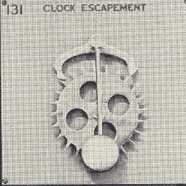
131. Clock escapement. The Seth Thomas clock exhibit opposite this section makes use of a type of clock escapement very similar to this, the only difference being a slight change in the shape of the pallets. The escape wheel, which turns in a clockwise direction, is supplied with long, pointed teeth. As it turns, the pallets alternately come in contact with the teeth, and cause the pendulum to swing.
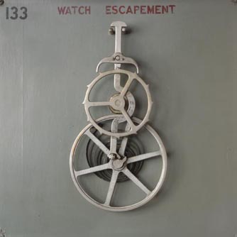
132. Watch escapement. The escapement in watches operates on the same principle as that in clocks, though a balance wheel is used instead of a pendulum. The anchor shaped piece with two horns is called the pallet. First one horn of the pallet, then the other,locks with the teeth of the escape wheel as it revolves. The unlocking is accomplished by a lever attached to the pallet. The action of this lever is controlled by a balance wheel which gets its action from the coiled spring often called a "hair spring." The lever is alternately engaged and released with the balance wheel by means of the small pin. Not only ingenuity, but the greatest accuracy and delicacy is required of the machinery used in the art of watchmaking.
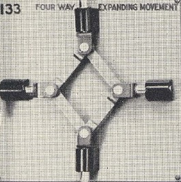
133. Four-way expanding movement. When motion is given to any one of the arms, the remaining three move the same distance.
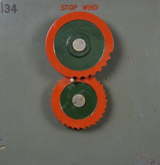
134. Stop wind. As the disk carrying ratchet teeth revolves, the pin attached to it carries the upper disk forward the distance of one tooth. After the last tooth is advanced, the pin rests against the outer edge of red disk and is held in that position against rotation. Flyback of red wheel represents running down of spring. This movement is used in watches to prevent overwinding the spring which causes breakage.
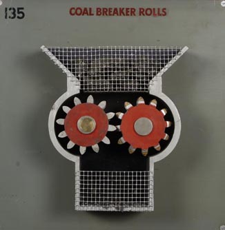
135. Coal breaker rolls. Connected with every commercial coal mine is a breaker plant for breaking and sorting the coal. Rolls of this type are placed in the top of the breaker building. The coal is led to the rollers and dumped in the top or hopper where it is broken by the rotation of the toothed rolls.
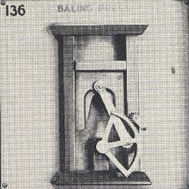
136. Baling press. This hand press is used for pressing cotton, waste paper and other material into a baling form to be tied for handling. The motion given through the hand crank is transmitted to the press by means of the toothed sector and rod connected with it at a greatly multiplied power.
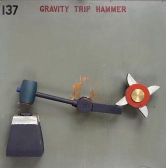
137. Gravity trip hammer. The hammer is lifted by the revolution of the toothed cam, four times to each revolution. Force of blow depends upon weight and length of drop of hammer head. This is one of the first types of power-driven forging hammers.
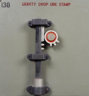
138. Gravity drop ore stamps. Sharp falls of the vertical rod are derived from the mutilated rotating wheel or pinion. This pinion acts upon the teeth in the rod and raises it until all teeth have meshed; then the rod falls.
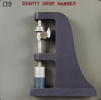
139. Gravity drop hammer. The rod is raised by the action of the revolving cam against the green lift collar. These are used for crushing rock to extract the ore and are generally mounted in gangs, having a large number in line.
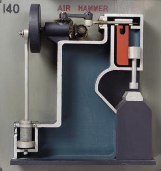
140. Air hammer. The head of this hammer is attached to a piston A, and is made to work in cylinder B, by the intermittent releasing of compressed air into the cylinder above and below by the slide-valve on top. The air is supplied from the air pressure chamber into which it has been forced by the air pump. When pump piston C is in up position, air enters through D and is compressed as piston descends through valve in bottom of cylinder. The air pump is driven by a crank attached to the black revolving disk on driving shaft. This type hammer is used for heavy duty forging and can also be operated by steam pressure.
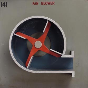
141. Fan blower. This is the well known type of fan blower used for forced air draught on ventilating systems. By the revolution of the central shaft and attached fan blades, air is drawn in at the center of the casing through the inlet and forced out under pressure through the spout.
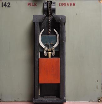
142. Pile driver. The earliest form of pile driver. The driver head is lifted by hooks to a sufficient height. Then the hooks are released by pressure of hook arms against the sides of the slot in the top of the frame, releasing the driver head. Its driving power depends on the weight of the driver and the height of drop since the force accumulates as the driver falls.
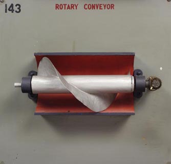
143. Rotary conveyor. A spiral blade is attached to the driving shaft so that as it rotates, the material being conveyed is pushed forward by the face of the blade in the direction of the arrow.
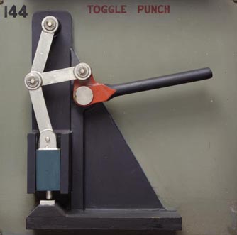
144. Toggle punch. The hand lever working upon the joint or horizontal connecting link through short center leverage at the end of handle exerts a terrific power on punch through toggle action, as explained in No. 92.
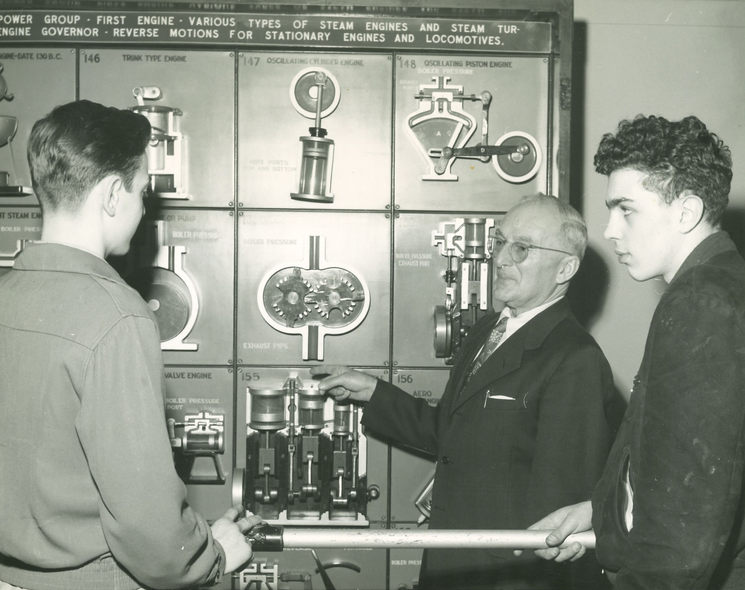
Section X Nos. 145-160, Steam power group, first engine, various types of steam engines and steam turbines, engine governor, reverse motion, for stationary engines and locomotives.
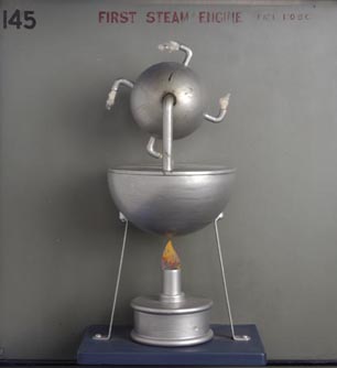
145. First steam engine. Date 130 B. C. Heron's engine, is now regarded as the first steam engine. Steam is generated in the lower vessel, or boiler and conducted into the globular vessel above by two bent tubes. These tubes also serve as pivots on which the globe revolves. Its rotation is caused by the steam escaping from the four bent arms and its direction is opposite to that of the steam travel.
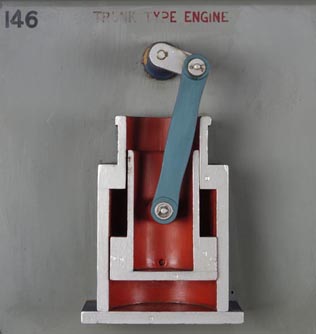
146. Trunk type engine. This is a simple form of the early type of trunk or atmospheric engine. Steam is admitted in bottom part of cylinder A through part B causing piston to rise. At end of tip stroke a jet of cold water is thrown into cylinder A through D, cooling steam and causing vacuum to draw piston down. The inertia stored in heavy fly wheel on shaft during up stroke of piston, causes crank C to travel over center for down stroke. It is now obsolete but was generally used before the introduction of the slide valve engine (See No. 154).
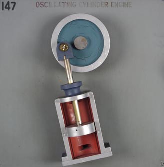
147. Oscillating cylinder engine. This engine is not a very efficient type. The cylinder is pivoted at its center to the engine frame, turning on pivot with an oscillating motion. Note the upper and lower parts in the back face of the cylinder to admit and exhaust the steam. As piston travels up, steam pressure is admitted through lower right port and exhausts through upper left port. As piston descends, steam is admitted through upper right port and exhausted through lower left port. The action of the piston rod drives the fly wheel to which it is attached by means of a crank. The inertia of the fly wheel carries the crank over the centers.
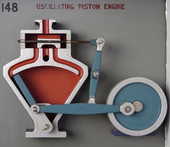
148. Oscillating piston engine. Steam enters at the top from the boiler and is admitted into the piston chamber A through steam ports by the action of the slide valve, B. The steam alternately strikes against the sides of the oscillating piston and passes through the exhaust port into the atmosphere. The crank C is attached to the piston shaft at bottom and is connected by a pitman rod D to the fly wheel. The crank pin operating in slot of valve rod E strikes the end of slot alternately and moves the upright valve arm F causing slide valve B to open and close steam ports.
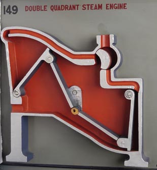
149. Double quadrant steam engine. This model is called the double quadrant steam engine because the two piston rods are attached to arms, which move in a quadrant or area equal to one quarter of a circle. Steam enters from the boiler at the top. The inlet valve A is attached to crank B on under side by a cam. Valve A allows steam to enter steam ports moving each piston arm alternately in a quadrant, turning crank B. On return stroke of red arms steam escapes into interior chamber C and through exhaust port into the air.
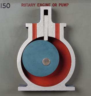
150. Rotary engine or pump. This is a very common form of rotary engine or pump. Steam entering at inlet on right exerts a pressure on the eccentric piston rotating in center of cylinder causing it to revolve until the longest point from the center indicated by arrow, passes the outlet, where steam passes into atmosphere. The slide A follows the piston and acts as a barrier against high pressure steam entering inlet. When used as a pump, piston is driven by power, water enters at boiler pressure inlet and is forced out exhaust port as piston revolves.
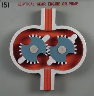
151. Elliptical gear engine or pump. Elliptical gears were explained briefly in No. 67. Steam enters at top from boiler and by exerting pressure on the arms of gears, the pistons rotate. As arms pass exhaust pipe entrance in turn, steam passes into the air. When used as a pump, the action is the same as in No. 150.
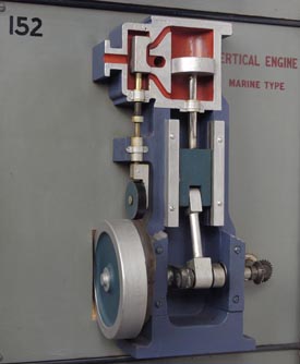
152. Vertical engine. Marine type. The slide valve which regulates the flow of steam into the piston chamber, is operated in this engine by a cam mounted on drive shaft. It is sometimes called a cam valve engine. The piston rod being driven by the force of the steam in cylinder turns the crank shaft attached to the cam causing it to revolve as in No. 154.
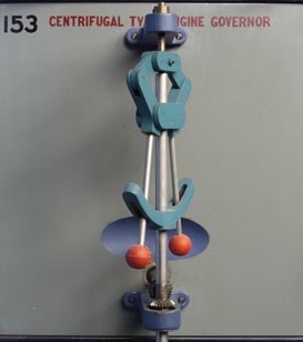
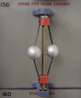
153. Spring type engine governor. A governor is a device to regulate the speed of an engine and was invented by James Watt. In this type the balls are attached to springs, having their upper ends fastened to a collar fixed on the central shaft and their lower ends fastened to a collar on a sliding sleeve. The springs are of such a tension that they will remain in one position for a required speed of the engine. When the engine exceeds this speed the balls are thrown outward by centrifugal force raising the sleeve stem and closing the valve so that the steam pressure is shut off. This keeps the speed of the engine constant.
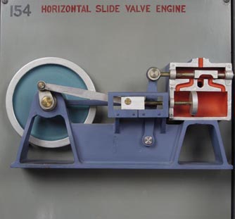
154. Horizontal slide valve engine. This is the well known type of reciprocating slide valve engine in universal use. Steam entering steam ports alternately by action of sliding valve, operates piston in cylinder. Attached to the piston rod is a crank and crank arm which drives the fly wheel. An eccentric on drive shaft operates the sliding valve through eccentric rod.
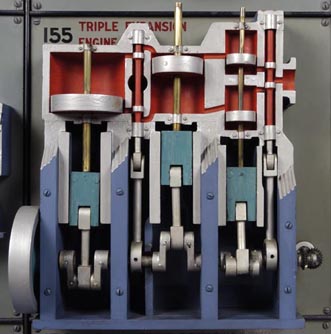
155. Triple expansion engine. Steam enters the cylinder on the right at high pressure causing piston rod to operate in regular way as in No. 152 and No. 154. After it performs its work, it is exhausted into low pressure cylinder in center and in turn into third low pressure cylinder on left. From here it is exhausted into atmosphere.
156. Aero radial engine. This is a radial engine of the airplane type. The vertical connecting rod with a disk type head is directly attached to the drive shaft crank A. This rod revolves completely with the crank. Note how the other four rods are connected to the disk. They are not rigid but oscillate as the disk turns. Valve actions and ignition are omitted as they are fully shown in Auto engine model No. 102. Firing rotation is every other cylinder in the 5, 7, or 9 cylinder types of engines.
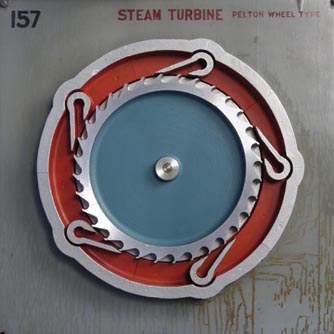
157. Steam turbine. Pelton wheel type. High pressure steam entering five steam inlets drives against the outside surface of the wheel making it revolve at a high speed. The speed is regulated by the opening of the steam port or inlet. Steam escapes through exhaust ports in casing.
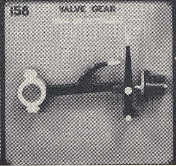
158. Valve gear. Hand or automatic. This is the first type used on stationary slide valve engines. Horizontal arm or handle is designed to be disconnected by hand from green head of valve rod. If this is done, vertical arm controls valve stem by hand operation. This change is necessary to enable the engineer to stop his engine off center or in a position where it will start again. This is done by watching crank shaft and closing both steam ports by action of vertical lever causing engine to stop in that position. Rods are then connected for automatic starting.
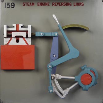
159. Steam engine reversing links. This is another type of valve gear called the reversing type and is most commonly used on locomotives. As you will note in the automatic action of this model, when the hand lever is thrown forward or backward it changes the position of the slide valve through action of slotted link motion, admitting steam in either end of cylinder as desired in order to start the engine forward or backward.
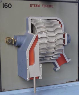
160. Steam turbine. This type of turbine is an improvement over No. 157. Through the multiple arrangement of the bucket wheels, steam enters through control valve striking first wheel fixed to shaft causing both to rotate. As this steam passes through, it strikes the stationary wheel in center and is deflected so that it strikes the third wheel, also fixed to shaft, again furnishing power to drive shaft.
Photos


Text excerpts from source materials
The source material is primarily pictures and diagrams, the historical information is located in the forward, collected here.
Prospectus of the American Artisan and Patent Record (1865) 23
The AMERICAN ARTISAN is a journal devoted to fostering the interests of Artisans and Manufacturers, encouraging the genius of inventors, and protecting the rights of Patentees. It is published every Wednesday morning, at No. 212 BROADWAY (corner of Fulton street), New York, by BROWN, COOMBS & CO., Solicitors of American and Foreign Patents.
The Proprietors of the AMERICAN ARTISAN believe that its varied and valuable contents are more instructive and interesting than those of any other weekly periodical of similar character published in either the United States or Europe. The AMERICAN ARTISAN contains numerous Original Engravings and Descriptions of New Machinery, etc., both American and Foreign-Histories of Inventions and Discoveries-Letters from Working-men in all parts of the World-Instructions in various Arts and Trades-Reliable Recipes for use in the Field, the Workshop, and the Household-News-items for Manufacturers-Practical Rules for Mechanics and Advice to Farmers-Illustrated Details of Useful and Ingenious "Mechanical Movements" and other Lessons for Young Artisans-the OFFICIAL List of "Claims " of all Patents issued weekly from the United States Patent Office-Reports of Law Cases relating to Patents; the whole forming an Encyclopedia of General Information on a variety of topics connected with the Industrial Arts, the Progress of Invention, etc.
Each number of the new series of the AMERICAN ARTISAN will contain sixteen pages of instructive and interesting reading matter, in which the progress of the arts and sciences will be recorded in familiar language, divested of dry technicalities and abstruse words and phrases. The columns of the AMERICAN ARTISAN will be rendered attractive by articles from the pens of many talented American writers upon scientific and mechanical subjects. In this journal is published regularly the OFFICIAL list of "claims" of all patents issued weekly from the United States Patent Office. Legal decisions in patent cases, tried in the United States Courts, will be periodically presented in the AMERICAN ARTISAN, together with descriptions of remarkable inventions recently patented at home or abroad.
507 Mechanical Movements by Henry T. Brown 3
The want of a comprehensive collection of illustrations and descriptions of MECHANICAL MOVEMENTS has long been seriously felt by artisans, inventors, and students of the mechanic arts. It was the knowledge of this want which induced the compilation of the collection here presented. The movements which it contains have been already illustrated and described in occasional installments scattered through five volumes of the AMERICAN ARTISAN, by the readers of which their publication was received with so much favor as was believed to warrant the expense of their reproduction with some revision in a separate volume.
The selection of the movements embraced in this collection has been made from many and various sources. The English works of Johnson, Willcock, Wylson, and Denison have been drawn upon to a considerable extent, and many other works—American and foreign—have been laid under contribution ; but more than one-fourth of the movements—many of purely American origin—have never previously appeared in any published collection. Although the collection embraces about three times as many movements as have ever been contained in any previous American publication, and a considerably larger number than has ever been contained in any foreign one, it has not been the object of the compiler to merely swell the number, but he has endeavored to select only such as may be of really practical value ; and with this end in view, he has rejected many which are found in nearly all the previously published collections, but which he has considered only applicable to some exceptional want.
Owing to the selection of these movements at such intervals as could be snatched from professional duties, which admitted of no postponement, and to the engravings having been made from time to time for immediate publication, the classification of the movements is not as perfect as the compiler could have desired; yet it is believed that this deficiency is more than compensated for by the copiousness of the Index and the entirely novel arrangement of the illustrations and the descriptive letter-press on opposite pages, which make the collection—large and comprehensive as it is—more convenient for reference than any previous one.
Forward to Mechanical Models book (1930) 8
Given to the Newark Museum by Louis Bamberger and Exhibited May-October, 1930
NOTE
In the spring of 1928 a pamphlet telling of an exhibit of working mechanical models to be seen in New York in the Boys' Department of a department store, came to Mr. Dana's attention. The maker of the exhibition, Mr. W. M. Clark, was interviewed and asked to lend the exhibit to the Museum, but it was found it would cost several hundred dollars for transportation and installation, and the exhibit was given up.
More than a year later Mr. Louis Bamberger talked with Mr. Dana about this same exhibit of Mechanical Models and Mr. Dana told Mr. Bamberger of his desire to show this exhibit in the Museum. Mr. Bamberger then decided to present these models, appropriately mounted and labeled, to the Museum.
The exhibit consists of ten sections, each measuring 5 feet 6 inches by 5 feet 8 inches, and weighing from 475 to 550 pounds apiece. In each section are sixteen small panels 15¼ inches square, each containing one or more movements. The sections are mounted on legs 16 inches high and are provided with covers both back and front so arranged that they can be handled exactly like a piano. The exhibit can be set up or taken down in a few hours. Each individual panel is connected electrically so that the visitor may set things in motion by pressing a button.
The Museum plans to lend the exhibit under certain conditions, to museums and other institutions which are equipped to set it up with the care required and to transport it.
Mr. W. M. Clark of South Orange is the inventor and maker of the Mechanical Exhibit.
From his early youth Mr. Clark has been interested in machines and has always had a great desire to visualize the science of mechanics. His work of twenty years or more in perfecting the exhibit was inspired by a wish to give to inventors and to all who deal in machine technique a short cut to their various ends. The first exhibit made by Mr. Clark is now in the Museum of the Peaceful Arts in New York City. The second set is a gift to the Newark Museum by Mr. Louis Bamberger.
Miss Virginia Downward, Head of the Science Department, aided by Mr. Clark, wrote the labels which present the story of each movement to the visitor.
This exhibit will be of tremendous interest not only to a city like Newark with its many industries, but to the State as well.
In connection with this exhibition the Public Library has an alcove of books, pamphlets and periodicals devoted to the subject.
BEATRICE WINSER
June 3, 1930
Forward to Manual of Mechanical Movements (1933 edition has different forward) 25
This collection of illustrations and descriptions of "Mechanical Movements" was originally published in the "American Artisan," a publication edited by Mr. Henry T. Brown, deceased, a prominent patent attorney, nationally known.
Mr. Brown was the senior member of Brown & Seward, patent attorneys, at 270 Broadway, New York City, enjoying an enviable reputation in the prosecuting of patent applications and all the work relative thereto.
A copy of this book, as originally published, was purchased, years ago, by the creator of "Mechanical Wonderland," Mr. W. M. Clark, of South Orange, New Jersey, a lover of mechanics who used it as a text book in his study of mechanics, which was his natural "Hobby."
Mr. Clark, through its help, acquired the foundation for a mechanical education, without schooling in the regular way, which inspired the conception, designing and building of a large exhibit, nationally known as "Mechanical Wonderland."
This exhibit visualizes the art and science of mechanics, so that those, like himself, who had no opportunity to get this education in the schools, can now get a quick grasp of it.
The Exhibit, "Mechanical Wonderland," is a collection of over 200 mechanical movements, devices and combinations of movements, showing every movement used in this art, either separately or in combination.
Several of these exhibits have been built, the first one being in the Science Museum of New York City, the last one being purchased by Mr. Louis Bamberger of Newark, New Jersey, and presented to the Newark Museum for permanent installation, where it has been viewed and studied by thousands of craftsmen, scientists, inventors, teachers and educational bodies, schools and colleges, together with those prominent in industries in the metropolitan area.
Over 135,000 people saw it in the "Grand Central Palace" in New York City in one week's period, when exhibited there. Inquiries were received from all parts of the United States, as well as from other countries concerning its installation in museums, educational institutions and industrial centers.
It has the endorsement of leading educators, colleges, industrial men and technical organizations throughout the country.
The Exposition, "A Century of Progress," affords a splendid opportunity to bring to the attention of all those interested in visual education, the application of this method in their own centers.
The inspiration gotten from "Mechanical Wonderland" will prove the worth of this volume, which inspired its building.
This edition is dedicated to "A Century of Progress." W. M. CLARK.
"The Museum" Volume 6, Number 3 Introduction by Katherine Coffey Published by The Newark Museum Summer 1954 16
John Cotton Dana's concept that a museum "should reflect our industries, be stimulating and helpful to our workers; promote an interest in the products of our shops," and his desire "to make adult Americans more pleased and proud of the mechanical achievements of their countrymen; and to arouse in the young an interest to do all kinds of things from the driving of a nail with a hammer to the construction of a motor car," lead him in 1926 to inquire about an exhibition of mechanical models on display in a New York department store. This exhibition, the life work of a New Jersey inventor, Mr. William M. Clark, consisted of panels on which were mounted one hundred-sixty working models, showing the fundamentals of mechanical movement, beginning with the first principles and covering the development, both practical and experimental, in a more or less natural sequence. What Mr. Clark had succeeded in doing was to condense into simple, compact, and easily operated models all the movements or combinations of movements used in mechanics. The first set he designed and constructed went to the New York Museum of Science and Industry, known at that time, in 1929, as The Museum of Peaceful Arts. This set now belongs to the Museum of Science, Boston. After Mr. Dana's death in 1929, Mr. Louis Bamberger ordered a second set of this "dictionary of mechanical movements" for the Newark Museum.
The models have been on exhibition continuously since 1930 with a few interruptions when they were lent to Mr. Clark for the Chicago World's Fairs of 1933 and 1934, and to the Massachusetts Institute of Technology in 1937 for display during the Annual Meeting of the Society for the Promotion of Engineering Education.
The thousands of people who have viewed this exhibition in the past twenty-four years have found considerable enjoyment in studying the mechanical operations presented effectively in it. It gives us pleasure to bring to our members and friends the following history of the principles of mechanical movements prepared by Kenneth Gosner of our Science Department Staff.
KATHERINE COFFEY, Director
Mechanical Models: A Collection of the Newark Museum By Kenneth L. Gosner 16
For most of us who are not trained engineers, the insides of a clock, a typewriter, or the mysteries hidden under the hood of a modern automobile present a picture of baffling complexity and even confusion. It is usually enough if the machine does what it is intended to, if its parts move according to the engineer's design. When this does not occur, when the machine fails, we are lost, frustrated, and usually annoyed. Then we anxiously call for the mechanic. Constantly we are confronted by the latest marvels of a highly technological era. If we are not familiar with the machines themselves we are at least familiar with their resulting product. Surprising then that an understanding of the principles of mechanical movements, which are so important in our civilization, has become more and more the province of engineers and mechanics alone.
The mechanical fittings of our culture result from the application of but a few principles, a few compared to the multitude of devices based on them. The inclined plane, lever, wedge, and pulley, together with the wheel and axle and the screw, are often called the six elements of mechanical movement—the six "simple machines." They provide the basis for mechanical invention. Nor are these the exclusive property of mankind or the product of his imagination alone. Simple machines may be found in the animal kingdom and elsewhere in nature. To take a familiar example—the mosquito. The mosquito flies and walks by manipulating the levers that make up her leg and wing attachments. The same mosquito, if she has the opportunity, makes effective use of a wedge when she punctures the skin in search of nourishment. Birds, which have been flying since Jurassic times or more than a hundred million years before man's labored efforts to get off the ground were successful, raise their wings by an arrangement of bone, muscle, and tendon which approximates the pulley in principle. When animals first climbed up out of the sea to conquer land habitats they very probably used the principle of the inclined plane.
Elementary machines, as well as fundamental mechanical movements and such complex pieces of machinery as an automobile engine, are shown in an operating exhibit of Mechanical Models in the Museum. One hundred-sixty movements and inventions are shown, and the photographs illustrating this text are taken from the exhibition. Historically the exhibit may be said to cover the period from man's earliest use of tools other than his own hands to the present age of internal combustion engines, turbines, and steam locomotives.
Examples of the use of the inclined plane, lever, and wedge are found abundantly in nature, and these few simple machines were employed by early man in the fashioning of tools. The use of mechanical devices goes back far beyond the limits of recorded history. The inclined plane and the lever were perhaps the first mechanical elements put to work. The principle of the wedge, which is really a form of the inclined plane, came into use when early human hunters and fishermen sharpened sticks to make the first spears. Later the wedge formed the basis of the sharp cutting edges of stone knives and projectile points.
As long as man followed a meager existence gathering the roots, nuts, berries, and fruits that grew around him, or was satisfied to fill out this vegetable diet with game and fish, his technology remained a relatively simple one. Later he began to perfect the techniques of agriculture, growing his own crops of corn and rice and domesticating dogs, pigs, and horses. But man's progress in improving the tools with which he worked went slowly. The discovery of fire gave him a means of improving the qualities of some of the tools that he already had and of using previously untried raw materials in perfecting new implements. The use of metals began with the smelting of simple ores and the pounding into useful shapes of native metals. The inclined plane, lever, and wedge, unassisted by other mechanical elements, continued to serve as the foundation of applied mechanics even into the period of ancient civilization. With simple mechanisms the Egyptian architects of 5000 years ago built the pyramids. During most of this long struggle, muscle power provided the force to accomplish human undertakings. Manpower alone raised tons of granite and limestone blocks into the fantastic pyramids of ancient Egypt, hundreds of thousands of men laboring for twenty years or more to accomplish this.
Special thanks to
- William A. Peniston, Librarian/Archivist (retired), The Newark Museum of Art, New Jersey
- Katherine Barrett, Assistant Curator, Collections, Museum of Science, Boston
- South Orange Historical Preservation Society, South Orange, NJ
Open Questions
- Were there more than 2 collections made? or other related items?
- What did W. M. Clark do professionally? We lack most biographical details.
Bibliography
This information and files are presented for the convenience of future readers. All materials are believed to be in public domain, and no copyright is implied. Please contact the site author if you feel it should be removed.
1 Millar, W. (1858) Patent 21800, IMPROVEMENT IN SEWING-MACHINES US Patent Office (Lists Henry T. Brown as witness, demonstrating his involvement in patent trade)
2 Brown, Henry T (editor) (1864) Table of Mechanical Movements American Artisan and Illustrated Journal of Popular Science p56, Brown, Coombs & Co.
First appearance of Mechanical Movements
3 Brown, Henry T (1868) Five Hundred and Seven Mechanical Movements Published by Brown, Coombs & Co, Office of the "American Artisan" archive.org
4 (1928) Puzzles of Modern Machinery Are Shown at Museum Exhibit New York Times
5 (1928) Moving Models Show How Autos Operate New York Times
6 (1930) Machine Models Shown in Newark New York Times
7 (1930) Collection of reports, photographs, and other materials related to the Museums of the Peaceful Arts, 1912-1930. Smithsonian Libraries
8 Clark, William M., and Virginia Downward, (1930) Mechanical Models: A Series of Working Models on the Art and Science of Mechanics. The Newark Museum
9 (1930) Standard Mechanical Movements Product Engineering Magazine p272
10 (1930) Standard Mechanical Movements Product Engineering Magazine p312
11 (1933) Ad in magazine promoting Mechanical Wonderland exhibit in 1934 Chicago World Fair Popular Science Magazine
12 DUFFUS, R.L. (1933) The Fair: A World of Tomorrow New York Times
NY Times Magazine article on Century of Progress World's Fair, 1933-1934
13 (1930-1942) A collection of materials relating to the New York Museum of Science and Industry New York Historical Society
14 Clark, William M. (1943) A Manual of Mechanical Movements Garden City Publishing
Note the content of the book is Five Hundred and Seven Mechanical Movements, with title pages removed and a forward added. 2
15 Juran, J.M. (1944) On The Technician's Bookrack New York Times (Book Review of A 'A Manual of Mechanical Movements')
16 Gosner, Kenneth L. (1954) "THE MUSEUM" Volume 6, Number 3 The Newark Museum Cornell , Newark Library
17 Cornell University & Boston Museum of Science (2005) Photos of partial Clark Collection and KMODDL (Kinematic Models for Design Digital Library)
18 Holden, Sarah (2009) Best-available video showing Clark Collection of Mechanical Movement at Boston Museum of Science
19 Eckstein, L. Blog page on history of William M. Clark's series of mechanical models
20 automatablog.com (2008) Article on Clark Collection
21 Peniston, William A. (2024) Private email correspondence
22 John Cotton Dana Wikipedia, retrieved 2024
23 Brown, Henry T (1865) Prospectus of the American Artisan American Artisan, Page 16 (p24 in record), retrieved 2024
24 "Scientific Items Gleam in New Home" New York Times (1936)
Article text suggests the Clark exhibits are included: "... beneath them is an array of levers, pulleys, inclined planes, ratchets, hydraulic devices and gears which work at the push of a button."
25 Clark, William M. (1933) A Manual of Mechanical Movements Garden City Publishing
Note the content of the book is Five Hundred and Seven Mechanical Movements, with title pages removed and a forward added. This forward has more historical details than 1943 edition. 2